Fuse:
• Main, F1-30 amp , blade-type
• Charg e circuit, F2-25 amp , blade-type
• Optional head light kit, 10 amp , blade-type
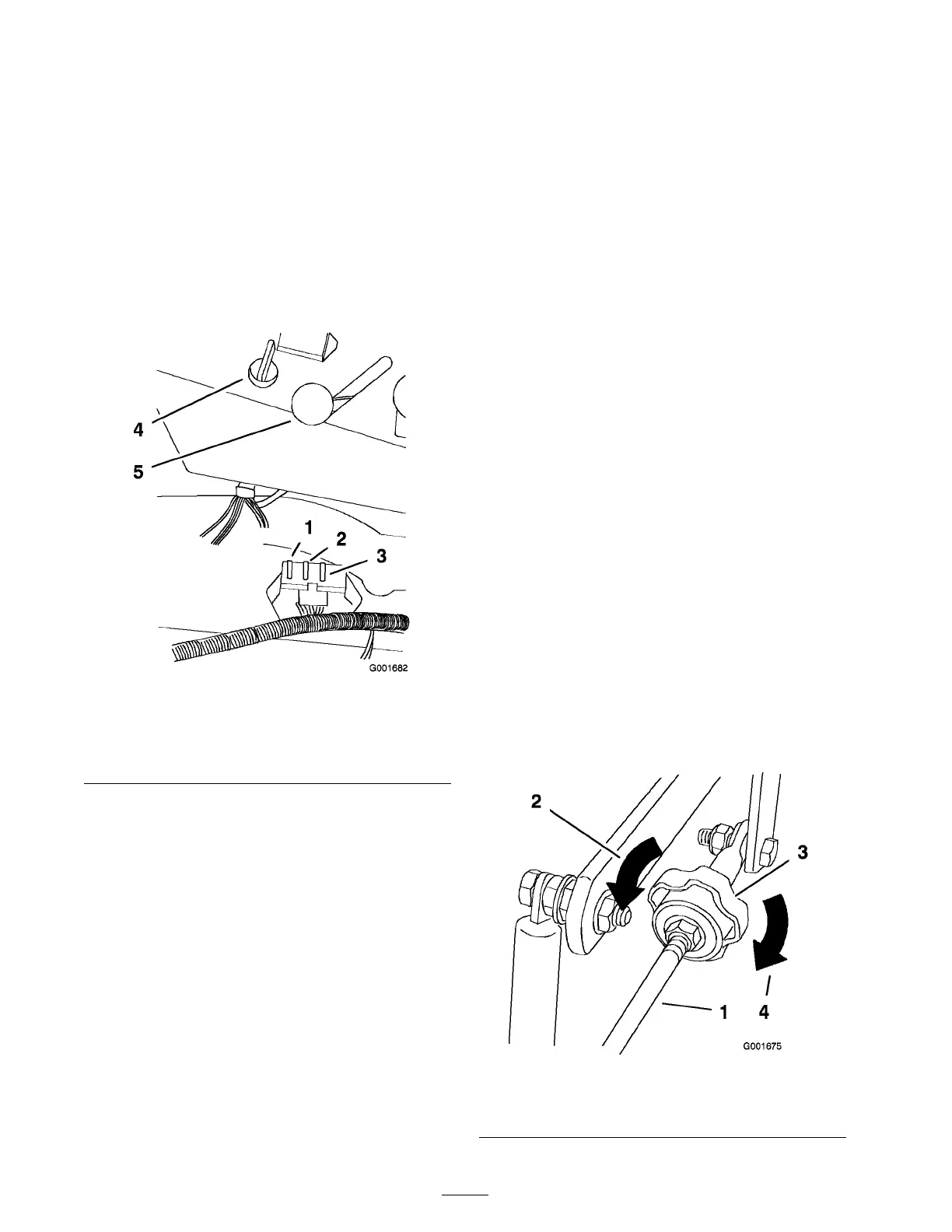
1. Raise the seat to g ain access to the fuse holder
( Figure 40 ).
2. T o re place the fuses , pull out on the fuse to
remo v e it.
3. Install a new fuse ( Figure 40 ).
Figure 40
1. Main, 30 amp
4. Ignition switch
2. Charge circuit, 25 amp 5. Throttle lever
3. For optional head light kit,
10 amp
Drive System
Maintenance
Adjusting the Tracking
Note: Deter mine the left and right sides of the
mac hine from the nor mal operating position.
T he mac hine has a knob for adjusting the trac king
located under the seat.
Important: Adjust the handle neutral and
h y draulic pump neutral bef or e adjusting
the tracking . R efer to Adjusting the Handle
Neutral in Contr ols System Maintenance ,
pa ge 39 and Adjusting the Hy draulic Pump
Neutral in Hy draulic System Maintenance ,
pa ge 40 .
1. Push both control lev ers forw ard the same
distance .
2. Chec k if the mac hine pulls to one side . If it
does , stop the mac hine and set the parking
brak e .
3. Unlatc h the seat and tilt the seat forw ard to
access the trac king knob .
4. T o mak e the mac hine g o right, tur n the knob
to w ards the rightside of the mac hine . R efer to
Figure 41 .
5. T o mak e the mac hine g o left, tur n the knob
to w ards the leftside of the mac hine . R efer to
Figure 41 .
6. R e peat adjustment until the trac king is cor rect.
Figure 41
1. Pump rod 3. Tracking knob
2. Turn this way to track left 4. Turn this way to track right
34