2. Stop the engine , remo v e the k ey , and w ait for
all mo ving par ts to stop before lea ving the
operating position.
3. R emo v e the belt co v ers o v er the outside
spindles .
4. Loosen the fix ed idler ar m and adjust it to
reliev e the belt tension on the fix ed idler pulley
( Figure 48 ).
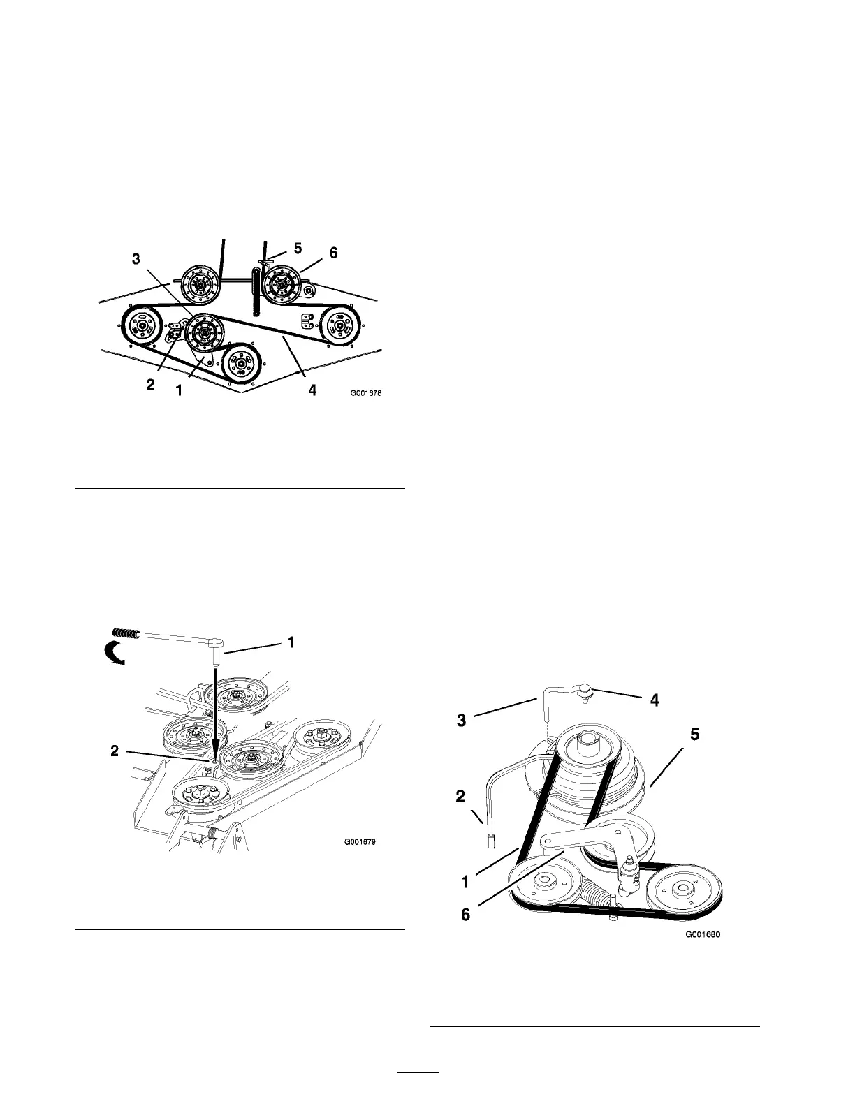
Figure 48
1. Fixed idler arm 4. Mower belt
2. Square hole 5. Belt guide
3. Fixed Idler pulley 6. Spring-loaded idler pulley
5. R emo v e the old belt.
6. Install the new belt through the belt guide and
on the pulleys ( Figure 48 ).
7. Inser t a ratc het with a shor t extension or a
break er bar into the square hole in the fix ed
idler ar m ( Figure 49 ).
Figure 49
1. Ratchet with short
extension or breaker bar
2. Square hole
8. T o increase the belt tension, rotate the ratc het
or break er bar countercloc kwise to mo v e
the fix ed idler ar m until y ou feel increased
resistance and the spring-loaded idler pulley
stops mo ving .
Note: Do not increase the belt tension
bey ond the point where the fix ed idler ar m
stops .
9. W hile holding the belt in tension, tighten the 2
bolts that secure the fix ed idler ar m.
10. R emo v e the ratc het or break er bar from the
square hole in the fix ed idler ar m.
11. Install the belt co v ers o v er the outside spindles .
Replacing the Pump Drive
Belt
Chec k the pump dri v e belt for w ear after ev er y
50 operating hours .
1. R emo v e the mo w er belt first; refer to R e placing
the Mo w er Belt.
2. R emo v e the bolt from the clutc h stop and
unplug the clutc h electrical wire ( Figure 50 ).
3. Pull the spring loaded idler to the side .
4. R emo v e the traction belt from the engine and
the h y draulic pump pulleys ( Figure 50 ).
5. Install the new belt around the engine and the
h y draulic pump pulleys ( Figure 50 ).
6. Pull the spring-loaded idler to the side and
align the belt.
7. R elease the pressure on the spring loaded idler
( Figure 50 ).
8. Install the mo w er belt.
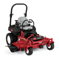
Figure 50
1. Belt 4. Bolt
2. Clutch electrical wire 5. Clutch
3. Clutch stop 6. Idler
38