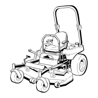
Figure 48
1. Cutting edge 3. Wear/slot forming
2. Curved area
Checking for Bent Blades
1. R otate the blades until the ends face forw ard
and bac kw ard ( Figure 49 ). Measure from a
lev el surface to the cutting edg e , position A , of
the blades ( Figure 49 ). Note this dimension.
Figure 49
2. R otate the opposite ends of the blades forw ard.
3. Measure from a lev el surface to the cutting
edg e of the blades at the same position as in
ste p 1 . T he difference betw een the dimensions
obtained in ste ps 1 and 2 m ust not ex ceed
1/8 inc h (3 mm). If this dimension ex ceeds
1/8 inc h (3 mm), the blade is bent and m ust be
re placed. R efer to R emo ving the Blades and
Installing the Blades .
A blade that is bent or dama ged could
br eak apar t and could seriousl y injur e or
kill y ou or bystander s.
• Al w ays r eplace bent or dama ged
blade with a new blade.
• Nev er file or cr eate shar p notches in
the edges or surf aces of blade.
Removing the Blades
T he blades m ust be re placed if a solid object is
hit, if the blade is out of balance , or the blade
is bent. T o ensure optim um perfor mance and
contin ued safety confor mance of the mac hine , use
g en uine T oro re placement blades . R e placement
blades made b y other man ufacturers ma y result in
non-confor mance with safety standards .
Hold the blade end using a rag or thic kly-padded
glo v e . R emo v e the blade bolt, cur v ed w asher ,
blade stiffener , and blade from the spindle shaft
( Figure 50 ).
Figure 50
1. Rotational direction of right
cutting blade
6. Fastening direction,
counter threaded bolt
2. Right cutting blade 7. Blade bolt, left cutting
blade
3. Blade stiffener 8. Fastening direction, normal
threaded bolt
4. Curved washer 9. Left cutting blade
5. Counter threaded blade
bolt, right cutting blade
10. Rotational direction of left
cutting blade.
Sharpening the Blades
1. Use a file to shar pen the cutting edg e at both
ends of the blade ( Figure 51 ). Maintain the
original angle . T he blade retains its balance if
38