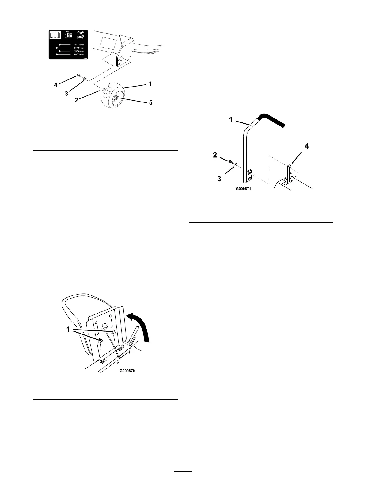
Figure 14
1. Gage wheel
4. Nut
2. Stud 5. Wheel nut and washer.
Do not remove.
3. Washer
B . Select a hole so that the g ag e wheel is
positioned to the nearest cor responding
height-of-cut desired ( Figure 14 ).
3. Install the stud n ut and w asher ( Figure 14 ).
4. R e peat the adjustment on the other g ag e
wheels .
Positioning the Seat
T he seat can mo v e forw ard and bac kw ard.
P osition the seat where y ou ha v e the best control
of the mac hine and are most comfor table .
1. Raise the seat and loosen the adjustment knobs
( Figure 15 ).
2. Mo v e the seat to the desired position and
tighten the knobs .
Figure 15
1. Adjustment knobs
Adjusting the Motion
Control Levers
T he motion control lev ers can be adjusted higher
or lo w er for maxim um operator comfor t.
1. R emo v e the 2 screws and cur v ed w ashers
holding the control lev er to the control ar m
shaft ( Figure 16 ).
2. Mo v e the control lev er to the next set of holes .
Secure the lev er with the 2 screws and cur v ed
w ashers . T he cupped side of the w asher should
be to w ard the control ar m shaft ( Figure 16 ).
3. R e peat the adjustment on the other control
lev er .
Figure 16
1. Control lever 3. Curved washer
2. Screw
4. Control arm shaft
Pushing the Machine by
Hand
Important: Al w ays push the machine
by hand. Nev er to w the machine because
dama ge may occur .
To Push the Machine
1. Diseng ag e the blade control switc h and mo v e
the control lev ers to the neutral loc k ed position
and apply the parking brak e .
2. Stop the engine , remo v e the k ey , and w ait for
all mo ving par ts to stop before lea ving the
operating position.
3. Pull the tw o b ypass lev ers up and push them
until the w asher on the rod passes through the
slot. Push the lev ers do wn to loc k them in
place ( Figure 17 ).
4. Diseng ag e the parking brak e to push the
mac hine .
18