13. W hen the front-to-rear blade slope is cor rect,
tighten the jam n uts ( Figure 43 and Figure 45 ).
14. R ec hec k the side-to-side lev el of the mo w er;
refer to Lev eling the Mo w er from Side-to-Side .
15. Chec k the height of the anti-scalp rollers; refer
to Adjusting the Anti-Scalp R ollers .
Removing the Mower
1. P ark the mac hine on a lev el surface .
2. Diseng ag e the blade control switc h and mo v e
the control lev ers to the neutral loc k ed position
and apply the parking brak e .
3. Stop the engine , remo v e the k ey , and w ait for
all mo ving par ts to stop before lea ving the
operating position.
4. Lo w er the height-of-cut lev er to the lo w est
position.
5. R emo v e the hair pin cotter and clevis pin from
the front tr union y ok es ( Figure 46 ).
Figure 46
1. Hairpin cotter and clevis
pin
2. Front trunion
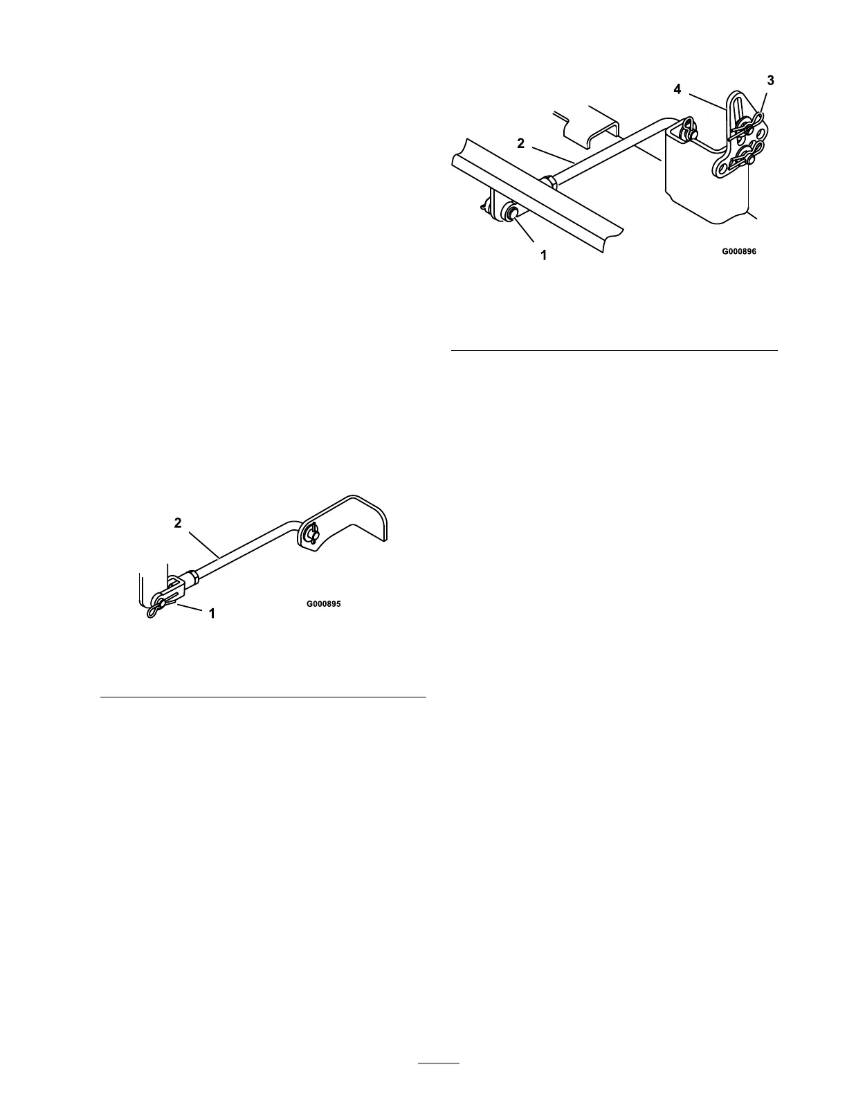
6. R emo v e the hair pin cotter and clevis pin from
the rear tr union rod ( Figure 47 ) on eac h side
of the mo w er .
7. R emo v e the hair pin cotter and w asher at
the mo w er lev eling brac k ets ( Figure 47 ) on
eac h side of the mo w er . Note whic h hole
the lev eling brac k et is mounted in for future
installation. Slide the brac k ets off of the
mounting pin.
Figure 47
1. Hairpin cotter and clevis
pin
3. Hairpin cotter and washer
2. Rear trunion rod 4. Leveling bracket
8. Slide the mo w er rearw ard to remo v e the
mo w er belt from the engine pulley .
9. Slide the mo w er out from under neath the
tractor .
Note: R etain all par ts for future installation.
Inspecting the Belts
Inspect all belts ev er y 100 hours .
Chec k the belts for crac ks , fra yed edg es , bur n
marks , or any other damag e . R e place damag ed
belts .
Squealing when the belt is rotating, blades slipping
when cutting g rass , fra yed belt edg es , bur n marks ,
and crac ks are signs of a w or n mo w er belt. R e place
the mo w er belt if any of these conditions are
evident.
Replacing the Mower Belt
1. Stop the engine , set the parking brak e , remo v e
the k ey , and disconnect the spark plug wire(s)
from the spark plug(s).
2. Set the height-of-cut at 1-1/2 inc h (38 mm).
3. R emo v e the belt co v ers o v er the outside
spindles .
4. Pull the idler pulley in the direction sho wn in
Figure 48 and roll the belt off of the pulleys .
Note: Do not remo v e the spring .
33