original angle . T he blade retains its balance if
the same amount of material is remo v ed from
both cutting edg es .
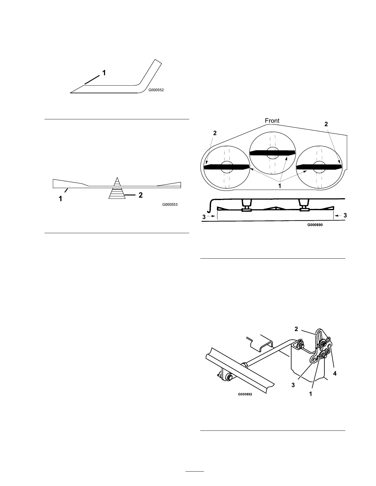
Figure 39
1. Sharpen at original angle
2. Chec k the balance of the blade b y putting it on
a blade balancer ( Figure 40 ). If the blade sta ys
in a horizontal position, the blade is balanced
and can be used. If the blade is not balanced,
re peat the shar pening procedure on the hea vier
side until the blade is balanced.
Figure 40
1. Blade 2. Balancer
Installing the Blades
1. Install the blade onto the spindle shaft
( Figure 38 ).
Important: T he cur v ed par t of the blade
must be pointing up w ard to w ard the inside
of the mo w er to ensur e pr oper cutting .
2. Install the cur v ed w asher (cupped side to w ard
the blade) and blade bolt ( Figure 38 ). T or que
the blade bolt to 35-65 ft-lb (47-88 N·m).
Leveling the Mower from
Side-to-Side
T he mo w er blades m ust be lev el from side to side .
Chec k the side-to-side lev el any time y ou install
the mo w er or when y ou see an unev en cut on y our
la wn.
1. P osition the mo w er on a flat surface .
Diseng ag e the blade control switc h, set the
parking brak e , stop the engine , and remo v e the
k ey . Disconnect the spark plug wire(s) from
the spark plug(s).
2. Chec k the air pressure of all four tires . If
needed, adjust to the recommended inflation;
refer to Tire Press .
3. Set the height-of-cut at 3 inc h (76 mm).
4. Carefully rotate the blade(s) from side to side
( Figure 41 ). Measure betw een the outside
cutting edg es and the flat surface ( Figure 41 ).
If both measurements are not within 3/16 inc h
(4.75 mm), an adjustment is required; refer to
ste ps 5 and 6.
Figure 41
1. Blades side to side 3. Measure here
2. Outside cutting edges
5. R emo v e the hair pin cotter and w asher from
the lev eling brac k et ( Figure 42 ). T o lev el the
blade(s), re position the lev eling brac k et(s) in
a different hole and install the w asher and
hair pin cotter . ( Figure 42 ). A front hole lo w ers
the blade height and a rear hole raises its
height. Adjust both sides as required.
Figure 42
1. Hairpin cotter and washer 3. Front hole
2. Leveling bracket 4. Rear hole
6. Chec k the front-to-rear blade slope; refer to
Adjusting the F ront-to-R ear Blade Slope .
31