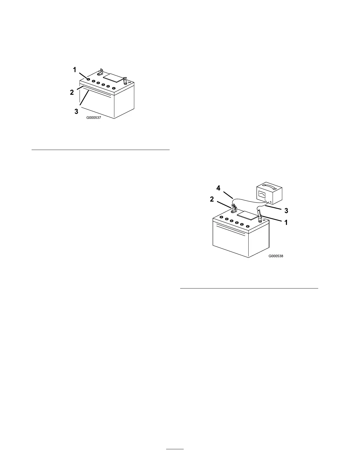
2. Look at the side of the batter y . T he electrolyte
m ust be up to the Upper line ( Figure 31 ).
Do not allo w the electrolyte to fall belo w the
Lo w er line ( Figure 31 ).
Figure 31
1. Vent caps
3. Lower line
2. Upper line
3. If the electrolyte is lo w , add the required
amount of distilled w ater; refer to Adding
W ater to the Batter y .
Adding Water to the Battery
T he best time to add distilled w ater to the batter y is
just before y ou operate the mac hine . T his lets the
w ater mix thoroughly with the electrolyte solution.
1. R emo v e the batter y from the tractor; refer to
R emo ving the Batter y .
Important: Nev er fill the batter y with
distilled w ater while the batter y installed in
the tractor . Electr ol yte could be spilled on
other par ts and cause cor r osion.
2. Clean the top of the batter y with a paper to w el.
3. R emo v e the v ent caps from the batter y
( Figure 31 ).
4. Slo wly pour distilled w ater into eac h batter y
cell until the electrolyte lev el is up to the Upper
line ( Figure 31 ) on the batter y case .
Important: Do not o v erfill the batter y
because electr ol yte (sulfuric acid) can
cause sev er e cor r osion and dama ge to the
chassis.
5. W ait fiv e to ten min utes after filling the batter y
cells . Add distilled w ater , if necessar y , until
the electrolyte lev el is up to the Upper line
( Figure 31 ) on the batter y case .
6. R einstall the batter y v ent caps .
Charging the Battery
Important: Al w ays k eep the batter y
full y charged (1.260 specific g ra vity). T his
is especiall y impor tant to pr ev ent batter y
dama ge when the temperatur e is belo w 32°F
(0°C).
1. R emo v e the batter y from the c hassis; refer to
R emo ving the Batter y .
2. Chec k the electrolyte lev el; refer to Chec king
the Electrolyte Lev el.
3. Mak e sure that the v ent caps are installed in
the batter y . Charg e the batter y for 1 hour at 25
to 30 amps or 6 hours at 4-6 amps . Do not
o v erc harg e the batter y .
4. W hen the batter y is fully c harg ed, unplug
the c harg er from the electrical outlet, then
disconnect the c harg er leads from the batter y
posts ( Figure 32 ).
Figure 32
1. Positive battery post
3. Red (+) charger lead
2. Negative battery post
4. Black (-) charger lead
5. Install the batter y in the tractor and connect the
batter y cables; refer to Installing the Batter y .
Note: Do not r un the tractor with the batter y
disconnected, electrical damag e ma y occur .
Servicing the Fuses
Ser vice Inter v al/Specification
T he electrical system is protected b y fuses . It
requires no maintenance; ho w ev er , if a fuse blo ws ,
c hec k the component/circuit for a malfunction
or shor t.
Fuse:
• Main F1–30 amp , blade-type
• Charg e Circuit F2–25 amp , blade-type
• Optional Headlight Kit–10 amp , blade type
28