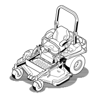
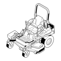
Figure87
1.Deckliftpedal
3.Transportlock
2.Heightofcutpin
6.Inserttheheightadjustmentpinintothe3inch(7.6
cm)cuttingheightlocation.
7.Releasethetransportlockandallowthedeckto
lowertothecuttingheight.
8.Raisethedischargechute.
9.Onbothsidesofthedeck,measurefromthelevel
surfacetothefronttipoftheblade(PostionA).
Themeasurementshouldread3inches(7.6mm)
(Figure88).
Figure88
1.3inches(7.6cm)atAis
correct
3.Measureherefromthe
bladetiptohardsurface
2.31/4inches(8.3cm)atB
iscorrect
4.MeasureatAandBon
bothsides
10.Ifneeded,loosenthewhizlocknutonthesideofthe
yokeandthejamnutontop.Finetunethescrew
adjusterbyturningittoget3inch(7.6mm)height
(seeFigure89).
Toincreasetheheight,turntheadjusterscrew
clockwise;todecrease,turncounterclockwise.
Figure89
1.Whizlocknut3.Jamnut
2.Adjusterscrew4.Yoke
11.Ifthefrontdecklinksdonothaveenoughadjustment
toachieveaccuratecutheight,thesinglepoint
adjustmentcanbeutilizedtogainmoreadjustment.
12.Toadjustthesinglepointsystem,loosenthetwo
boltsatthebottomoftheheightofcutplate.Refer
to
Figure90.
Figure90
1.Boltsatthebottomoftheheight-of-cutplate
13.Ifthedeckistoolow,tightenthesinglepoint
adjustmentboltbyrotatingitclockwise.Ifthedeck
istoohigh,loosenthesinglepointadjustmentbolt
byrotatingitcounterclockwise(Figure91).
57