AdjustingtheFront-ShockAssembly
Thefront-shockassemblyissetatthemiddlepositionandis
normallynotadjusted.
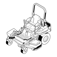
Toadjustthefront-shockassembly,opentheoorpanand
adjustitbyusingaspannerwrench(ToroPartNo.132-5069)
orslip-jointpliers(Figure40).
Figure40
1.Middleposition
3.Softride
2.Firmride
UsingtheDrive-WheelRelease
Valves
WARNING
Handsmaybecomeentangledintherotatingdrive
componentsbelowtheenginedeck,whichcould
resultinseriousinjury.
Shutofftheengine,removethekey,andwait
forallmovingpartstostopbeforeaccessingthe
drive-wheelreleasevalves.
WARNING
Theengineandhydraulicdriveunitscanbecome
veryhot.Touchingahotengineorhydraulicdrive
unitscancausesevereburns.
Waitfortheengineandhydraulicdriveunitstocool
completelybeforeaccessingthedrive-wheelrelease
valves.
Thedrive-wheelreleasevalvesarelocatedinthebackofeach
hydraulicdriveunit,undertheseat.
Note:Makesurethatthereleasevalvesareinthefully
horizontalpositionwhenoperatingthemachine,orsevere
damagetothehydraulicsystemcouldoccur.
1.Disengagetheblade-controlswitch(PTO)and
turntheignitionkeytooff.Movetheleverstothe
NEUTRAL-LOCKpositionandapplytheparkingbrake.
Removethekey.
2.Rotatetherelease-valveleversverticallytopushthe
machine(Figure41).
Note:Thisallowsthehydraulicuidtobypassthe
pump,enablingthewheelstoturn.
3.Disengagetheparkingbrakebeforepushingthe
machine.
Figure41
1.Verticaltopushthe
machine
2.Horizontaltorunthe
machine
4.Rotatetherelease-valvelevershorizontallytorunthe
machine(Figure41).
31