RemovingtheBlades
Bladesmustbereplacedifasolidobjectishit,ifthe
bladeisoutofbalance,orifthebladeisbent.To
ensureoptimumperformanceandcontinuedsafety
conformanceofthemachine,usegenuineToro
replacementblades.Replacementbladesmadeby
othermanufacturersmayresultinnonconformance
withsafetystandards.
1.Holdthebladeendusingaragora
thickly-paddedglove.
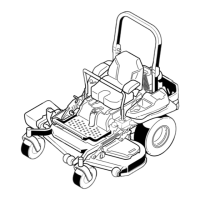
2.Removethebladebolt,thecurvedwasher,and
thebladefromthespindleshaft(Figure97).
g004536
Figure97
1.Sailareaoftheblade3.Curvedwasher
2.Blade4.Bladebolt
SharpeningtheBlades
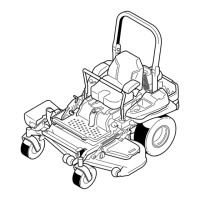
1.Usealetosharpenthecuttingedgeatboth
endsoftheblade(Figure98).
Note:Maintaintheoriginalangle.
Note:Thebladeretainsitsbalanceifthesame
amountofmaterialisremovedfrombothcutting
edges.
g000552
Figure98
1.Sharpenatoriginalangle.
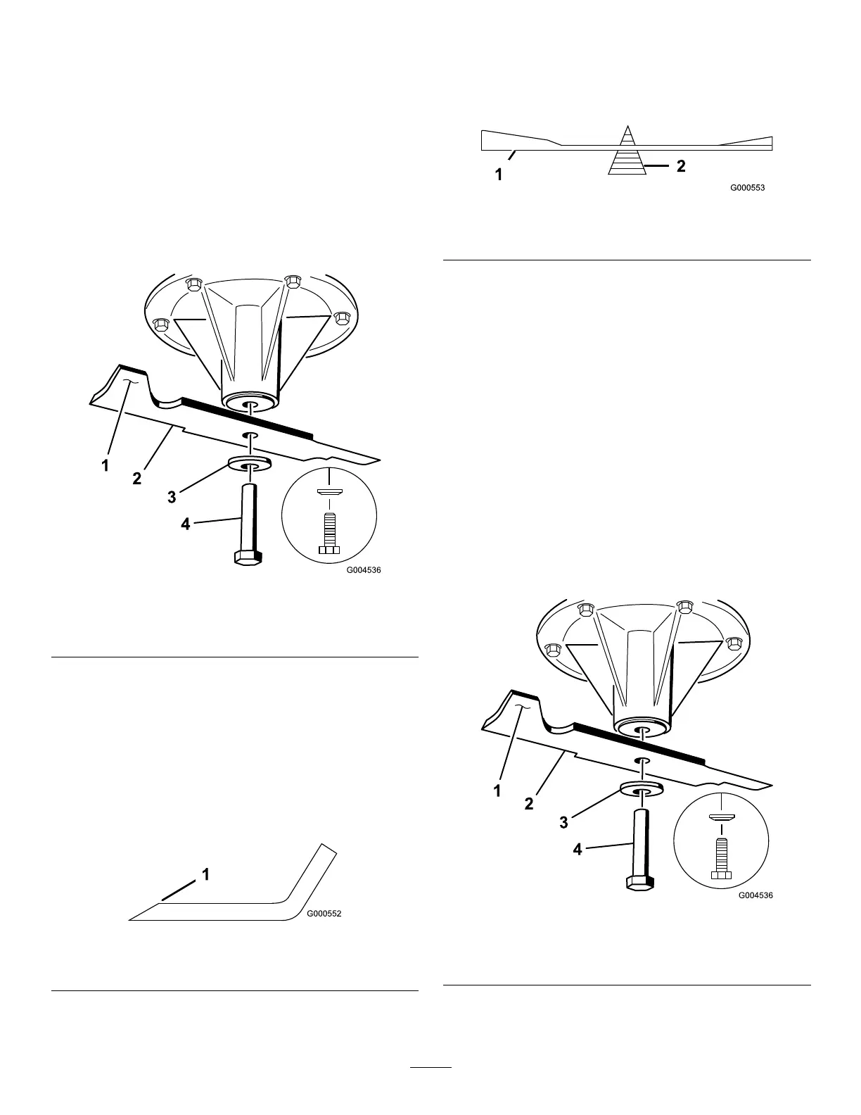
2.Checkthebalanceofthebladebyputtingitona
bladebalancer(Figure99).
Note:Ifthebladestaysinahorizontalposition,
thebladeisbalancedandcanbeused.
Note:Ifthebladeisnotbalanced,lesome
metalofftheendofthesailareaonly(Figure98).
g000553
Figure99
1.Blade2.Balancer
3.Repeatthisprocedureuntilthebladeis
balanced.
InstallingtheBlades
1.Installthebladeontothespindleshaft(Figure
100).
Important:Thecurvedpartoftheblade
mustbepointingupwardtowardtheinside
ofthemowertoensurepropercutting.
2.Installthespringdiskandbladebolt(Figure
100).
Note:Thespring-diskconemustbeinstalled
towardthebolthead(Figure100).
3.Torquethebladeboltto115to150N∙m(85to
110ft-lb).
g004536
Figure100
1.Sailareaoftheblade3.Springdisk
2.Blade4.Bladebolt
68