Installation
5
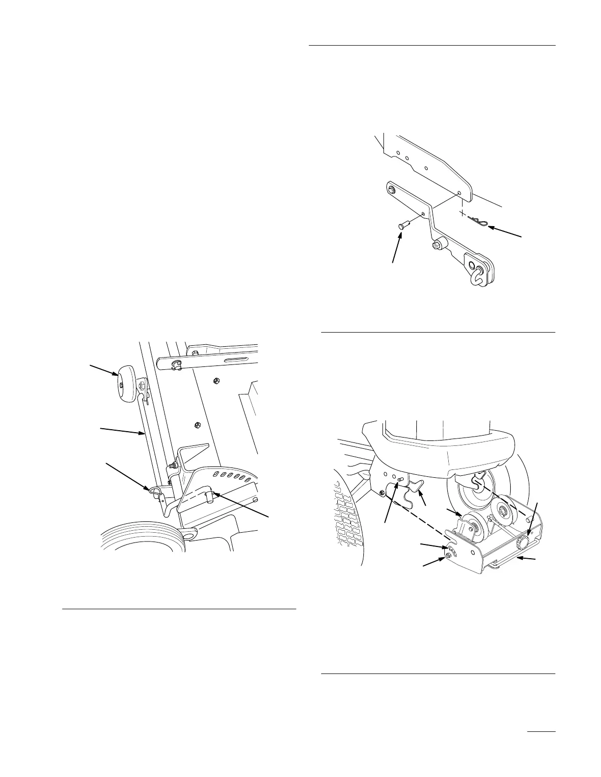
2. Lower the rear center wheel (if not already
lowered). Do this by:
A. Removing the hairpin cotter from the wheel
rod (Fig. 4).
B. Lifting the rear of the deck.
C. Pulling the rod toward the outside of the
mower, inserting the end of the rod into the
hole in the height–of–cut plate (Fig. 4), and
then installing the hairpin cotter into the
second hole of the wheel rod as shown
(Fig. 4).
3. Set the height of the (2) front mower wheels and
turn the wheels parallel to the mower by
removing the clevis pins and hairpin cotters,
then turning and raising or lowering the wheels
until you can put the clevis pins and hairpin
cotters in the third position from the top (Fig. 3).
m–3579
1
2
3
4
Figure 4
1. Hairpin
cotter
2.
Wheel rod
3. Hole
in height–of–cut plate
4. Rear
center wheel
4. Position the tractor and mower side by side, with
the mower on the right–hand side of the tractor.
5. Set the parking brake, raise the attachment lift,
and turn the ignition key to “STOP” to stop the
engine. Remove the ignition key.
6. If you have previously had a snowthrower, blade
or tiller attached to the attachment lift, remove
the two clevis pins on each side of the
attachment lift (Fig. 5).
2
1
m–3433
Figure 5
1. Clevis
pin
2.
Hairpin cotter
7. Attach the pulley box if it is not already on the
tractor. Make sure the latches on the tractor’s
front Attach–A–Matic are open (Fig. 6). Then
slide the pulley box into the Attach–A–Matic
latches and seat it. Close the latches.
m–3463
1
22
3
4
5
6
7
Figure 6
1. Attach–A–Matic
latches
2.
Pulley box
3.
Idler pulley
4.
Belt tension release arm
5.
Belt tension adjustment
knob
6.
Belt tension indicators
(one on each side)
7. Attach–A–Matic
button
(one on each side)