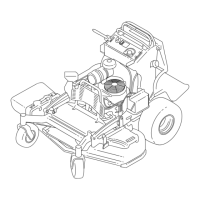
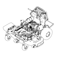
g006530
Figure77
1.Cuttingedge3.Wear/slotforming
2.Curvedarea4.Crack
CheckingforBentBlades
1.Rotatethebladesuntiltheendsfaceforward
andbackward.
2.Measurefromalevelsurfacetothecutting
edge,positionA,oftheblades(Figure78).
g000975
Figure78
1.Measureherefromblade
tohardsurface
2.PositionA
3.Rotatetheoppositeendsofthebladesforward.
4.Measurefromalevelsurfacetothecuttingedge
ofthebladesatthesamepositionasinstep2
above.
Note:Thedifferencebetweenthedimensions
obtainedinsteps2and3mustnotexceed3mm
(1/8inch).
Note:Ifthisdimensionexceeds3mm
(1/8inch),replacetheblade.
WARNING
Abladethatisbentordamagedcould
breakapartandcouldcriticallyinjure
youorbystanders.
•Alwaysreplaceabentordamaged
bladewithanewblade.
•Donotleorcreatesharpnotchesin
theedgesorsurfacesoftheblade.
RemovingtheBlades
Replacethebladesiftheyhitasolidobject,orifthe
bladeisoutofbalanceorbent.
1.Placeawrenchontheatofthespindleshaftor
holdthebladeendusingaragorthicklypadded
glove.
2.Removethebladebolt,bushing,andbladefrom
thespindleshaft(Figure79).
g295816
Figure79
1.Sailareaoftheblade
4.Bushing
2.Blade5.Bladebolt
3.Flatofthespindleshaft
SharpeningtheBlades
1.Usealetosharpenthecuttingedgeatboth
endsoftheblade(Figure80).
Note:Maintaintheoriginalangle.
Note:Thebladeretainsitsbalanceifthesame
amountofmaterialisremovedfrombothcutting
edges.
52
 Loading...