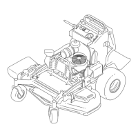
B.Removethebolt,washer,springwasher,
andclutch(Figure42).
C.Applyanti-seizecompoundtothecrank
shaft,theninstallthebolt,washer,spring
washer,andaspacer(T oropartno.
136-5411)totheshaft(Figure88).
g226598
Figure88
1.Crankshaft4.Springwasher
2.Spacer
5.Bolt
3.Washer
D.Applydielectricgreasetotheconnectorand
useacabletietosecureittothemachine.
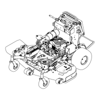
InstallingtheMowerDeck
1.Slidethemowerdeckunderthemachine.
2.Rotatethecasterwheelsrearward.
3.Connectthedeckhangerstotheliftplatesusing
the2bolts,2nuts,and2washersthatyou
retainedforeachsideofthemowerdeck.
Note:Mountthefronthangerbracketsonthe
outsideofthefrontliftarmsfor52-inchdecks
(Figure85).Mountthefronthangerbracketson
theinsideofthefrontliftarmsfor60-inchdecks
(Figure86).
Note:T orquetheboltsto38to49N∙m(28to
36ft-lb).
4.Installthe2boltsthatyouretainedtoconnect
thestrutbrackettotheframe(Figure84).
Note:T orquetheboltsto61to75N∙m(45to
55ft-lb).
5.Installthemower-deckbelt;refertoReplacing
theMower-DeckBelt(page46).
6.Levelthemowerdeck;refertoLevelingthe
MowerDeckfromSidetoSide(page56)and
LevelingtheMowerDeckfromFronttoRear
(page56).
LevelingtheMowerDeck
PreparingtheMachine
Ensurethatthemowerdeckislevelanytimeyou
installthemowerdeckorwhenyouseeanuneven
cutonyourlawn.
Levelthemowerdecksidetosidebeforeadjusting
thefront-to-rearslope.
1.Parkthemachineonalevelsurface,disengage
thePTO,andengagetheparkingbrake.
2.Shutofftheengine,removethekey,and
disconnectthespark-plugwiresfromthespark
plugs.
3.Checkthetirepressureofbothdrivetires;refer
toCheckingtheTirePressure(page42).
4.Checkthemowerdeckforbentblades;remove
andreplaceanybentblades;refertoServicing
theCuttingBlades(page51).
5.Lowerthemowerdecktothe76mm(3inch)
height-of-cutposition.
CheckingtheMowerDeck
Side-to-SideHeight
1.Adjusttherear-tirepressure.
2.Ensurethatthebladesarenotbent;referto
CheckingforBentBlades(page52).
3.Positionthebladessidetoside.
4.MeasureattheBandClocationsfromalevel
surfacetothecuttingedgeofbladetips(Figure
89).
g006888
Figure89
1.Measurefromalevel
surface
2.Measurethebladeat
pointsBandC
5.ThedifferencebetweenmeasurementsBandC
shouldbenomorethan6mm(1/4inch).
55
 Loading...