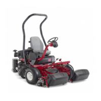
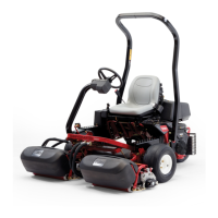
Greensmaster 3250--D
Hydraulic System (Rev. I)
Page 4 -- 85
1. Hose assembly
2. Hose assembly
3. O--ring
4. 90
o
hydraulic fitting
5. Orificed hydraulic fitting
6. Cotter pin
7. Clevis pin
8. Lift arm
9. Hydraulic cylinder
10. Retaining ring
11. Cylinder pin
12. Frame
13. O--ring
14. Flow control valve (if equipped)
15. O--ring
16. O--ring
17. 90
o
hydraulic fitting
18. Washer
Figure 54
HYDRAULIC CYLINDER
14
1
11
12
6
7
2
4
10
10
9
15
13
3
18
8
16
5
17
18
Rear Cylinder Removal (Fig. 54)
1. Before removing any parts from the hydraulic sys-
tem, park the machine on a level s urface, engage the
parking brake, lower the cutting units, and stop the en-
gine.
CAUTION
Before continuing further, read and become fa-
miliar with General Precautions for Removing
and Installing Hydraulic System Components.
2. Label all hydraulic connections for reassembly.
3. Disconnect hose assemblies and O--ring from the
hydraulic fittings. Allow hoses to drain into a suitable
container.
4. Remove cotter pin from the clevis pin. Pull clevis pin
with washers from the hydraulic cylinder and lift arm.
5. Support hydraulic cylinder to prevent it from drop-
ping.
A. Remove a retaining ring from the cylinder pin.
B. Pull cylinder pin from the hydraulic cylinder and
frame.
C. Remove hydraulic cylinder from the frame.
Rear Cylinder Installation
1. Position hydraulic cylinder tho the frame. Insert cyl-
inder pin with retaining ring through the frame bracket
and cylinder. Secure pin with retaining ring.
2. Position clevis of the hydraulic cylinder to the lift
arm. Insert clevis pin with washers through the cylinder
clevis and secure with cotter pin.
3. Connect hose assemblies and O--rings to the hy-
draulic fittings. Tighten hose connections.
Hydraulic
System
 Loading...