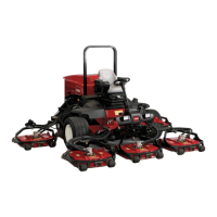
Figure7
1.Left-handpusharm5.Capscrewsandwashers
2.Castorarm
6.Balljoint
3.Balljointmount7.Jamnut
4.Chainmount
4.Haveanotherpersoncarefullypushdownonthe
pusharmuntiltheholesintheballjointmountline
upwiththeholesinthecastorarm.Immediately
slidea4x4inchblockofwoodbetweenthetopof
thepusharmandtheundersideofthechassis.
WARNING
Suddenreleaseofthepusharmcouldcause
injury.
Makesurethatthewoodenblockdoesnotslip
out.
5.Securetheballjointmountandchainbrackettothe
castorarmwiththecapscrews,atwashers,and
angenutspreviouslyremoved.Positiontheat
washerstotheoutsideofthecastorarm.Mountthe
chainbracketintheforwardsetofholes.
6.Tightenthelargejamnutsecuringtheballjointto
thepusharm.Whentighteningthejamnut,holdthe
balljointstraighttopermitproperoscillationduring
raisingandloweringofthecuttingunit.Carefully
removethewoodblockholdingthepusharmdown.
5
ConnectingtheDriveShaftto
theCuttingUnitGearBox
Partsneededforthisprocedure:
2
Bolt,5/16x1-3/4inches
2
Locknut,5/16inches
2
Rollpin,3/16x1-1/2inches
Procedure
Important:Thedriveshaftyokesmustbeexactly
inlinewitheachotherwhentheouteryokeis
installedonthegearboxsplinedPTOshaft.
Removethesleeveandchangetheyokepositionif
thealignmentisnotcorrect.Misalignmentofthe
twoyokeswillshortenthelifeofthedriveshaftand
causeunnecessaryvibrationwhenthecuttingunit
isoperated.
1.Lineuptheholesintheyokeandinputshaftofthe
gearbox.Slidetheyokeontotheshaftandsecure
themtogetherwitharollpinand2capscrews(5/16
x1-3/4inches)andlocknuts(5/16inch)(
Figure8).
Figure8
1.Driveshaftyokes
3.Rollpinandcapscrews
2.Yokesinphase
2.MountthePTOshieldtothetopofthecutting
unitgearboxmountingplatewiththe2self-tapping
screwspreviouslyremoved.
11

 Loading...


