MAINTENANCE
7 - 8 Snow Commander Service Manual
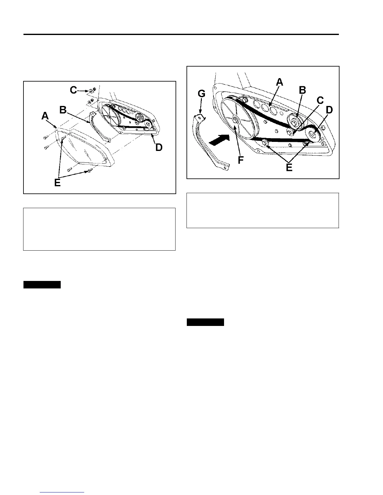
4. Remove the two self-tapping screws, three cap
screws, one washer, and three locknuts that
secure the drive belt cover to the snowthrower
frame (Figure 91). Set the drive belt cover aside.
Figure 91
m-5064
5. Remove the left rotor guard (Figure 91) and save
it for installation in step 10.
The left rotor guard acts as a water seal
for the drive. Do not assemble the drive cover without
installing this part or the drive belt will slip and fail.
6. Remove the old drive belt from the engine pulley
and the idler pulley (Figure 92).
Figure 92
m-5063
7. Push down on the idler pulley and remove the
drive belt from the rotor pulley (Figure 92).
8. Push down on the idler pulley and route the new
drive belt around the rotor pulley (Figure 92).
9. Release the idler pulley and route the drive belt
over the two belt guides, around the engine pulley,
and between the idler pulley and the roller (Figure
92).
The drive belt must be on top of the roller
and the two belt guides as shown in Figure 92.
10. Install the left rotor guard.
11. Install the drive belt cover. Tighten the fasteners
securely, but do not overtighten.
NOTE: Install the diamond-shaped washer as shown
in Figure 91 and Figure 93.
(A) Drive Belt Cover
(B) Left Rotor Guard
(C) Washer (diamond-
shaped on some
models)
(D) Snowthrower Frame
(E) Self-Tapping Screws
Important
(A) Brake Arm Assembly
(B) Idler Pulley
(C) Roller
(D) Engine Pulley
(E) Belt Guides
(F) Rotor Pulley
(G) Left Rotor Guard
Important