ENGINE REMOVAL / INSTALLATION
3 - 4 Snow Commander Service Manual
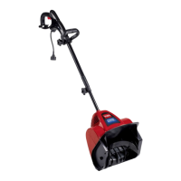
13. Remove 2 bolts right in front of the engine. It will
be necessary to reach under the unit to access the
locknuts (Figure 27).
Figure 27
3428-0242
14. The engine and engine cradle will now lift out of
the chassis.
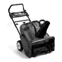
15. Remove the 3 locknuts shown in Figure 28 to
access the recoil starter. Also the engine cradle
and engine can be separated if necessary.
Figure 28
3428-0247
Assembly
Reverse the order.
If the engine was removed from the cradle, torque the 4
bolts around the crankshaft to 170 - 220 in. lbs (1355 -
2483 N·cm).
However, leave the bolts securing the engine cradle
slightly loose until the engine location can be checked
and adjusted.
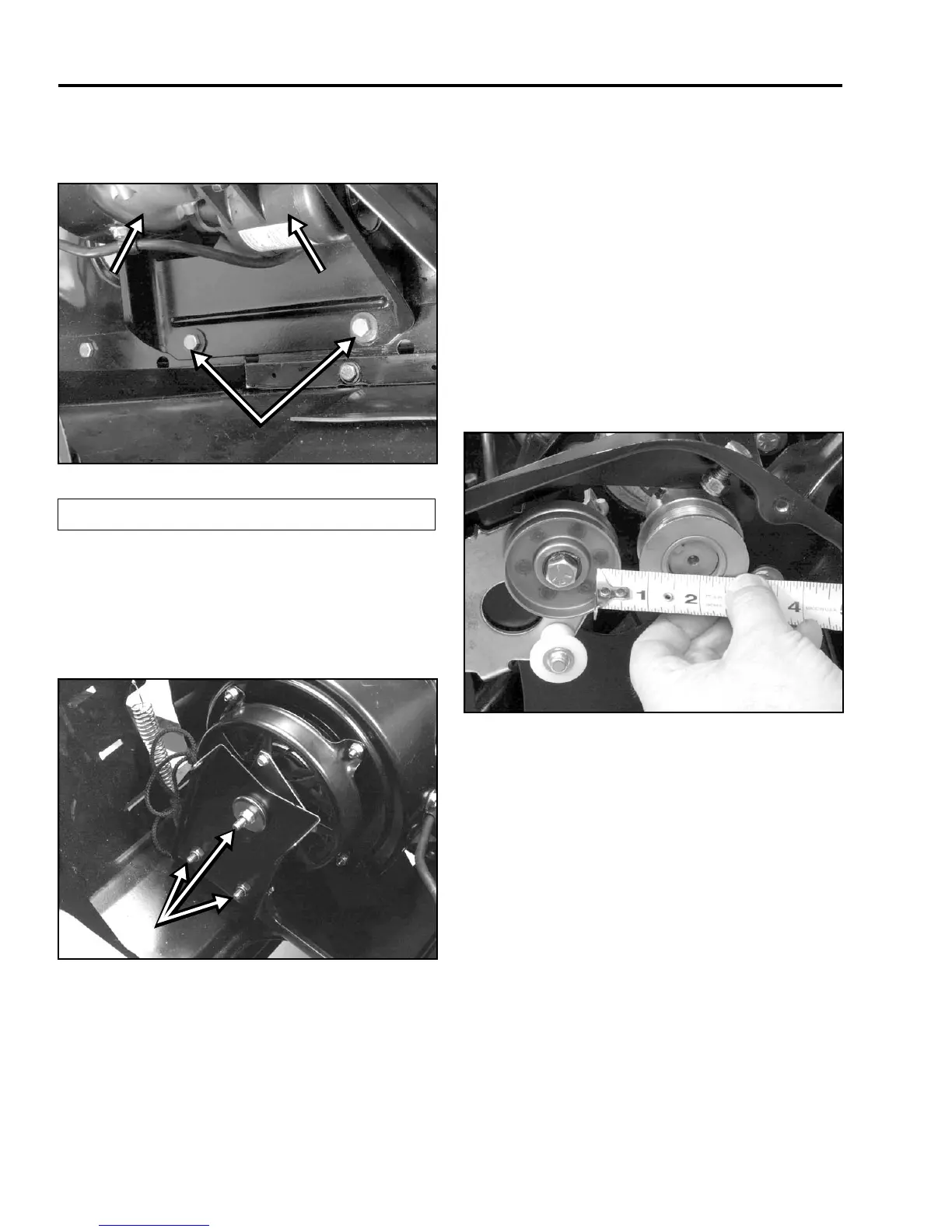
Adjust the engine to achieve the same gap between
the idler pulley and engine pulley, as measured
previously (Figure 29). Then snug the mounting
screws to hold the engine in place.
Figure 29
3428-0232
To assure the engine is properly located in the housing,
measure the distance between the carburetor and the
left side of the opening. When the engine is correct, the
gap should be .030” (.762mm) (Figure 30). NOTE: If
this check is not done, the choke lever may hang up on
the shroud.
(A) Engine (B) Starter Motor
A
B