6
Toro TEMPUS Controller 4
_
6
_
8
Connecting the Valves
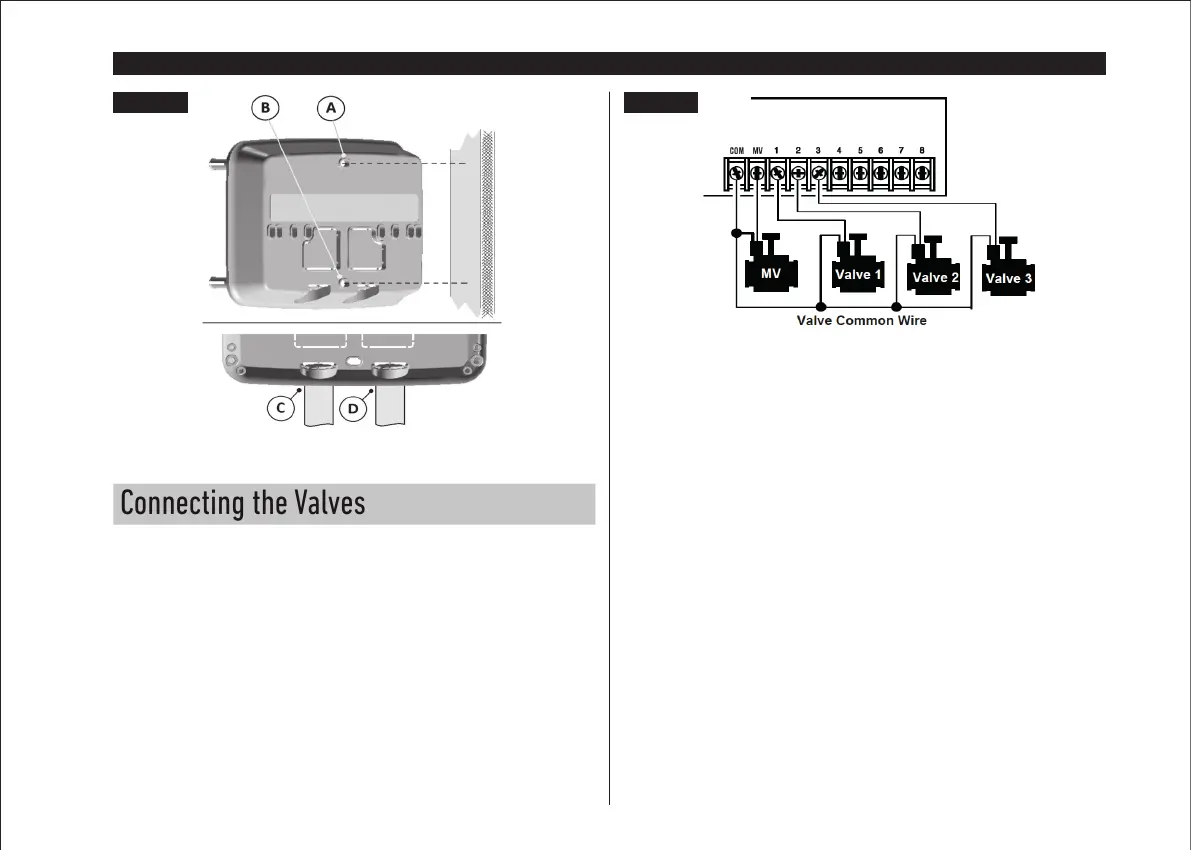
1. Route the valve wires or wire cable from the valves, into the controller cabinet.
Note: although up to 2 mm
2
wire can be used, it is recommended to use a 2 mm
2
multi-wire sprinkler valve connection. This cable is insulated for direct burial and
is color-coded to simplify installation. It can be routed directly into the controller
through the access hole provided for valve wire conduit (if conduit is not used).
2. Attach the red color-coded wire from each valve solenoid (either solenoid wire
can be used connection) to a single cable wire. This is called the “Valve Common”
wire. See Figure 2.
3. Attach a separate cable wire to the remaining wire from each valve solenoid.
Note the wire color code used for each valve and the watering station it controls.
You will need to have this information when connecting the valve wires to the
controller.
4. Secure all wire splices using wire nut connectors. To prevent corrosion and
possible short circuits, always use an insulated wire nut, grease cap or similar
waterproofing method.
5. At the controller end of the valve connection cable, strip back 6 mm of insulation
from all cable wires.
6. Secure the Valve Common wire to the terminal labeled COM. Connect the
individual valve wires to the appropriate station terminals. Connect the master
valve wire (if applicable) to the terminal labeled MV.
Note: Connecting a master valve or pump start relay is optional and may not be
required for your sprinkler system.
Figure 1 Figure 2
BACK MODULE