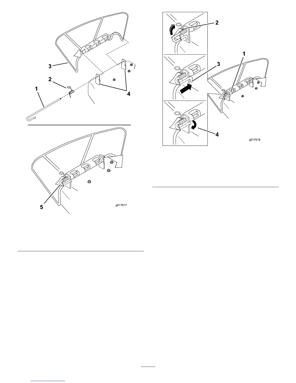
Figure57
1.Rod4.Deckbrackets
2.Spring5.Springinstalledoverthe
rod
3.Deector
2.Positionthenewdischargedeectorwiththebracket
endsbetweentheweldedbracketsonthedeckas
shownin
Figure57.
3.Installthespringontothestraightendoftherod.
Positionthespringontherodasshowninsothe
shorterspringendiscomingfromundertherod
beforethebendandgoingovertherodasitreturns
fromthebend.
4.Lifttheloopendofthespringandplaceitintothe
notchonthedeectorbracket(
Figure58).
Figure58
1.Rodandspringassembly
installed
3.Rod,shortend,moved
behindmowerbracket
2.Loopendofthespring
installedintothenotchin
thedeectorbracket
4.Shortend,retainedby
mowerbracket.
5.Securetherodandspringassemblybytwistingitso
theshortendoftherodcanbeplacedbehindthe
frontbracketweldedtothedeck(Figure58).
Important:Thegrassdeectormustbespring
loadedinthedownposition.Liftthedeector
uptotestthatitsnapstothefulldownposition.
43

 Loading...