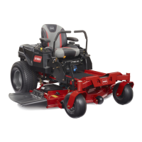
Product Overview
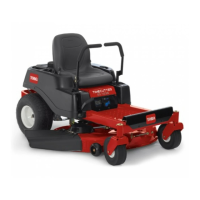
Figure 3
1. Seat
4. Height of cut lever 7. Anti-scalp wheel 10. Discharge chute
2. Control panel 5. Parking brake 8. Front castor wheel 11. Gas tank
3. Motion control levers 6. Mower deck
9. Footrest
12. Rear drive wheel
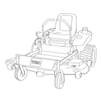
Controls
Become familiar with all of the controls Figure 4
and Figure 5 before y ou star t the engine and
operate the mac hine .
Figure 4
1. Motion control lever 3. Height-of-cut lever
2. Parking brake lever
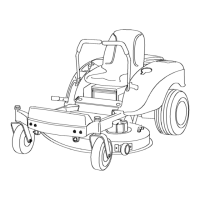
Figure 5
1. Ignition switch 4. Blade control switch
(power take-off)
2. Choke 5. Headlight—optional
3. Throttle
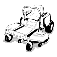
Parking Brake
T he parking brak e is automatically set when the
motion control lev ers are in the brak e position.
Alw a ys position the motion control lev ers into the
brak e position when y ou stop the mac hine or lea v e
it unattended.
11
 Loading...