T he machine can spin v er y rapidl y . T he
operator may lose contr ol of the machine
and cause per sonal injur y or dama ge to the
machine.
• Use caution when making tur ns.
• Slo w the machine do wn bef or e making
shar p tur ns.
Forward
1. R elease the parking brak e .
2. Mo v e the lev ers to the center , unloc k ed
position.
3. T o g o forw ard, slo wly push the motion control
lev ers forw ard ( Figure 12 ).
Note: T he engine will kill if the traction
control lev ers are mo v ed with the parking
brak e eng ag ed.
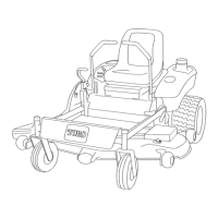
Figure 12
1. Motion control
lever-neutral lock position
3. Forward
2. Center unlock position 4. Backward
T o g o straight, apply equal pressure to both
motion control lev ers ( Figure 12 ).
T o tur n, release pressure on the motion control
lev er to w ard the direction y ou w ant to tur n
( Figure 12 ).
T he far ther y ou mo v e the traction control
lev ers in either direction, the faster the mac hine
will mo v e in that direction.
T o stop , pull the motion control lev ers to
neutral.
Backward
1. Mo v e the lev ers to the center , unloc k ed
position.
2. T o g o bac kw ard, slo wly pull the motion control
lev ers rearw ard ( Figure 12 ).
T o g o straight, apply equal pressure to both
motion control lev ers ( Figure 12 ).
T o tur n, release the pressure on the motion
control lev er to w ard the direction y ou w ant to
tur n ( Figure 12 ).
T o stop , push the motion control lev ers to
neutral.
Stopping the Machine
T o stop the mac hine , mo v e the traction control
lev ers to neutral and se parate to loc k, diseng ag e
the blade control switc h, and tur n the ignition k ey
to Off to stop the engine . Also set the parking
brak e when y ou lea v e the mac hine; refer to Setting
the P arking Brak e . R emember to remo v e the k ey
from the ignition switc h.
Important: Do not enga ge the par king
brak e while the machine is mo ving . Dama ge
to the dri v e system may occur .
Childr en or bystander s may be injur ed if
they mo v e or attempt to operate the tractor
while it is unattended.
Al w ays r emo v e the ignition k ey and set the
par king brak e when lea ving the machine
unattended, ev en if just f or a few min utes.
Adjusting the Height of Cut
T he height of cut is adjusted from 1-1/2 to
4-1/2 inc h (38 to 114 mm) in 1/2 inc h (13 mm)
increments b y relocating the clevis pin in different
hole locations .
1. Raise the height-of-cut lev er to the transpor t
position (also the 4-1/2 inc h (114 mm) cutting
height position) ( Figure 13 ).
2. T o adjust, remo v e the hair pin cotter and clevis
pin from the height-of-cut brac k et ( Figure 13 ).
3. Select the hole in the height-of-cut brac k et
cor responding to the height-of-cut desired,
and inser t the clevis pin ( Figure 13 ).
16
 Loading...