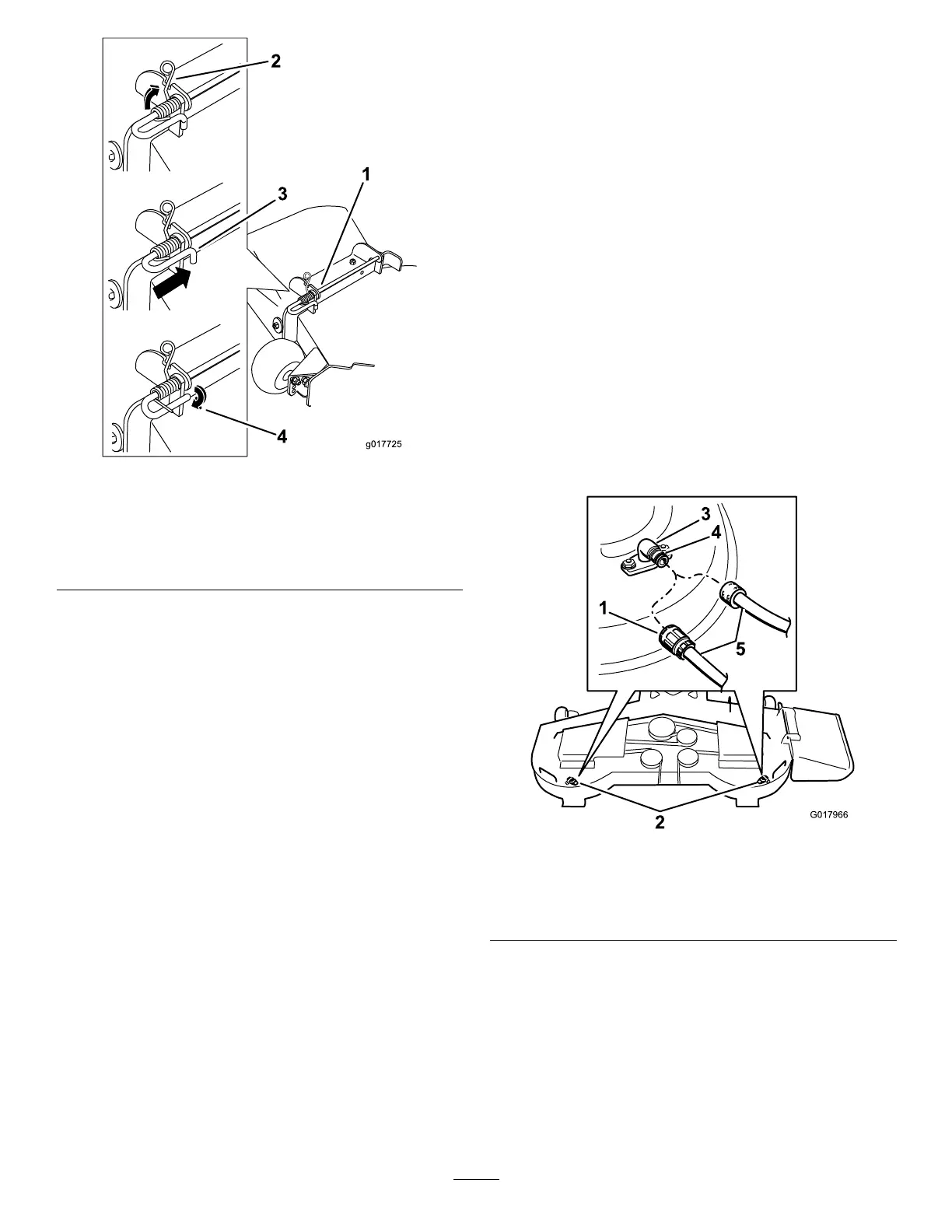
Figure71
1.Deectorassembly4.Spring
2.Deckbrackets
5.Springinstalledoverthe
rod
3.Rod
2.Positionthenewdischargedeectorassemblywith
thebracketendsbetweentheweldedbracketsonthe
deckasshowninFigure71.
3.Installthespringontothestraightendoftherod.
Positionthespringontherodasshowninsothe
shorterspringendiscomingfromundertherod
beforethebendandgoingovertherodasitreturns
fromthebend.
4.Liftthelongendofthespringandplaceitintothe
notchonthedeectorassemblybracket(
Figure72).
Figure72
1.Rodandspringassembly
partiallyinstalled
3.Rod,shortend,moved
behindmowerbracket
2.Longendofthespring
installedintothenotchin
thedeectorbracket
4.Shortend,retainedby
mowerbracket.
5.Securetherodandspringassemblybytwistingitso
theshortendoftherodcanbeplacedbehindthe
frontbracketweldedtothedeck(
Figure72).
Important:Thegrassdeectormustbespring
loadedinthedownposition.Liftthedeector
uptotestthatitsnapstothefulldownposition.
51
 Loading...