Do you have a question about the Toro TITAN ZX4820 and is the answer not in the manual?
Attach the rollbar supports to the mower frame and engine guard.
Assemble the pivot brackets to the rollbar structure.
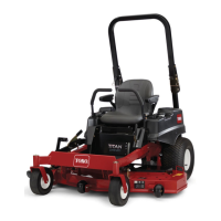
This document provides comprehensive setup instructions for the Toro TITAN ZX4820 and ZX5420 Zero-Turn-Radius Riding Mowers, covering initial assembly, critical adjustments, and final checks to ensure safe and proper operation. The manual is designed to guide users through the process of preparing their new mower for use, emphasizing safety and correct installation of key components.
The setup process begins with connecting the battery, a fundamental step for any new power equipment. This involves locating the battery and negative battery cable, removing the protective cap, and securing the negative battery cable to the negative battery post using the provided fasteners. This ensures the electrical system is properly connected and ready for operation.
Next, the manual details the setup of the motion control levers and the seat. The motion control levers, initially folded down for shipping, need to be raised to an upright position. This involves removing an upper bolt and washer, loosening a lower bolt, and then aligning the lever holes with the control arm shaft before re-installing the bolt and washer. Hand-tightening is recommended initially, with final adjustments and tightening performed later to ensure proper alignment and function. The seat setup is also crucial for operator comfort and safety. This involves placing the motion control levers in the outward, neutral lock position, removing hairpin cotters from the seat rod, sliding the seat rod out, rotating the seat 180 degrees, and reinstalling it. The interlock switch cable must then be connected to the seat, and the seat lowered into the operating position. After these steps, the control levers are returned to the center (neutral) position, and their alignment is verified and adjusted as necessary, with all fasteners tightened.
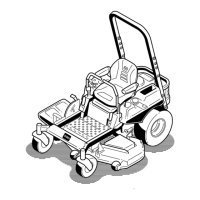
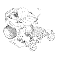
A significant portion of the manual is dedicated to installing the Roll Over Protection System (ROPS), a critical safety feature. This procedure requires several parts, including the rollbar, rollbar supports, pivot brackets, flat spacers, pivot pins with hairpins and lanyards, reinforcing brackets, large washers, various bolts (1/2 x 4-1/2 inches, 1/2 x 3-1/2 inches, 5/16 x 3-3/4 inches), cylindrical spacers, flat washers (1/2 inch, 5/16 inch), flange locknuts (1/2 inch, 5/16 inch), hex locknuts (1/2 inch), and conical and small rubber bumpers. The installation begins with attaching the rollbar supports. This involves locating the factory-installed brace between the engine and the rear wheel, loosening its locknut, and then attaching the rollbar support to the frame and the brace. It's important to leave bolts loose initially to allow for shifting and to ensure the cutout at the top of the support tube faces the rear of the machine, with the reinforcing bracket correctly oriented. The rollbar support is also attached to the engine guard.
Attaching the pivot brackets to the rollbar is the next step, again leaving bolts loose to allow for movement. Users are reminded to ensure locknuts are on the inside of the support tube and that the lanyard tab is angled away from the pivot bracket surface. The rollbar itself is then attached by inserting cylindrical spacers into the pivot holes of both rollbar supports, lifting the rollbar (with cutouts facing up), aligning its pivot holes with the spacers, and attaching it to the supports. A second person may be helpful for this step. The bolts are left loose enough for the rollbar to pivot freely. Finally, the rollbar is raised to the upright position and locked in place with both pivot pins, secured by hairpins.
The manual then outlines the "Making Final Adjustments" section, which specifies the torque requirements for various fasteners. This is crucial for ensuring the structural integrity and safety of the ROPS. Fasteners are tightened in a specific sequence, with precise torque values provided for bolts attaching pivot brackets to the rollbar and supports, rollbar supports to the frame and brace, braces to the machine frame, and the rollbar to the engine guard. A critical note warns against exceeding torque specifications to prevent structural damage. If not pre-installed, small rubber bumpers are pressed into holes on the back of the rollbar supports. The pivot pins are removed to ensure the rollbar pivots freely, and if not, the rollbar is removed to verify correct cylindrical spacer installation. Conical rubber bumpers, if not pre-installed, are installed inside the cutout at the top of the rollbar supports and secured with flange nuts. The rollbar is then locked in the upright position with pivot pins, and hairpins are inserted into the straight end of each pivot pin until they lock in place.
The final section, "Completing the Setup," covers a series of essential checks and remaining parts. This includes items like a hose coupling (not for CE models), a cut-off baffle (CE models only), bolts (5/16 x 5/8 inch, 54 inch CE units only), an ignition key, the Operator's Manual, the Engine Operator's Manual, and Operator Training Material. The procedure involves checking tire pressure, referring to the Operator's Manual for recommended inflation. The side discharge chute's packing restraint is removed, and the chute is lowered into place. Engine oil and hydraulic oil levels are checked before starting the engine, again referencing the Operator's Manual. Mower adjustment, specifically side-to-side level and front-to-rear blade slope, is also mentioned as a factory-set item that may require adjustment if cutting is uneven. Finally, users are instructed to review all remaining parts and keep them with the machine.
Throughout the manual, emphasis is placed on proper alignment, secure fastening, and adherence to torque specifications to ensure the mower operates safely and effectively. The step-by-step instructions, coupled with clear diagrams, aim to make the setup process straightforward for the user.
| Self-Propelled | Yes |
|---|---|
| Starter Type | Electric |
| Cutting Width | 48" (122 cm) |
| Transmission | Hydrostatic |
| Deck Material | Steel |
| Deck Washout Port | Standard |
| Mulching Capability | Optional |
| Cutting Height | 1.5" - 4.5" (3.8 - 11.4 cm) |