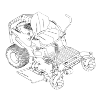
Figure5
1.Bolt(1/2x3–1/2inches)
(4)
4.Flatspacer(4)
2.Flatwasher(4)5.Flangelocknut(4)
3.Pivotbracket,notchfacing
up(4)
6.Rollbar,cutoutfacing
down
AttachingtheRollbar
1.Insertthecylindricalspacerinthepivotholesinboth
rollbarsupports(Figure6).
Figure6
1.Cylindricalspacer
2.Largepivothole
2.Lifttherollbarwiththecutoutsinendsofthe
tubefacingupandalignthepivotholeswiththe
cylindricalspacersintherollbarsupports.
Note:Asecondpersontoperformthenextstep
willbehelpful.
3.Attachtherollbartotherollbarsupportsasshownin
Figure7.Leavetheboltsjustlooseenoughtoallow
therollbartofreelypivot.
Note:Ensurethatthetabtowhichthelanyardis
attachedisangledawayfromthesurfaceofthepivot
bracket.
Figure7
1.Bolt(1/2x3–1/2inch)(2)3.Flangelocknut(2)
2.Pivotpinwithhairpinand
lanyard(2)
4.Raisetherollbarintotheuprightpositionandlockit
inplacewithbothpivotpinsasshownin
Figure8.
Figure8
1.Rollbar3.Hairpin
2.Pivotpin4.Rollbar,uprightandlocked
MakingFinalAdjustments
1.Tightenthefastenersintheorderspeciedinthe
followingtable.Figure4andFigure5willhelp
identifytheparts.
5
 Loading...