EasyManua.ls Logo

Toro Wireless RainSensor 53770 - User Manual

Toro Wireless RainSensor 53770
12 pages
To Next Page IconTo Next Page
Loading...
Introduction
The Toro Wireless RainSensor connects to your irrigation system controller/timer to
suspend automatic watering operation in the event of rain. Designed for ease of
installation, your sensor-controlled irrigation system will be up and running in minutes.
Before attempting the installation, please read through these instructions in their
entirety, and refer the installation instructions for your irrigation system controller/timer
in regards to connecting a rain sensor or rain switch. The Wireless RainSensor is
designed to work with either Normally Open or Normally Closed sensor circuits.
Important: Please note the following information regarding installation and use
of the Wireless RainSensor components:
The RainSensor Receiver is designed to operate with 24 V ac power only.
Connecting the Receiver wiring to 120/240 V ac power may result in severe
equipment damage.
Installation methods must comply with all applicable national and local building
codes. If you are unsure about proper wiring practices, have a qualified contrac-
tor perform the installation for you.
The Receiver cover should always be used when the Receiver is installed out-
doors.
The Sensor/Transmitter should never
be submerged in water or installed inside a
rain gutter.
Contents Page
Component Overview . . . . . . . . . . . . . . . .2
Quick Start Installation Instructions . . . . . .3
Detailed Installation Instructions . . . . . . . .4
• Mounting the Receiver . . . . . . . . . . . . .4
• Receiver Control Wire Connection . . .4-5
• Receiver Power Wire Connection . . . . .6
• Initial Receiver Testing . . . . . . . . . . . . .7
• Rainfall Adjustment . . . . . . . . . . . . . . .7
• Sensor/Transmitter Installation . . . . . .7
• Testing Signal Strength . . . . . . . . . . . .7
• Testing Control System Operation . . . .7
• Installing the Sensor/Transmitter . . . . .8
Wireless RainSensor Operation . . . . . . . .9
• Normal Operation . . . . . . . . . . . . . . . . .9
• Smart Bypass . . . . . . . . . . . . . . . . . . .9
• Power Down . . . . . . . . . . . . . . . . . . . .9
• Receiver Learn Mode . . . . . . . . . . . . . .9
Attention Required . . . . . . . . . . . . . . . .9
Battery Replacement . . . . . . . . . . . . . . .10
Changing Sensor/Transmitter Code . . . .10
Troubleshooting . . . . . . . . . . . . . . . . .10-11
Electromagnetic Compatibility . . . . . . . . .11
Specifications . . . . . . . . . . . . . . . . . . . . .12
Warranty . . . . . . . . . . . . . . . . . . . . . . . .12
Receiver
Sensor/Transmitter
Wireless RainSensor
Model 53770
User’s Guide
Question and Answer IconNeed help?

Do you have a question about the Toro Wireless RainSensor 53770 and is the answer not in the manual?

Toro Wireless RainSensor 53770 Specifications

Operating Environment IconOperating Environment
operating temperature range-20°F to 120°F
sensor/transmitter range300' line-of-site
Battery IconBattery
transmitter battery type2 x 3V cells - CR2032
average battery lifefive years
Power IconPower
receiver power input22–28 V ac/V dc, 100mA
relay contacts output3A at 24 V ac

Summary

Introduction

Important Installation and Usage Notes

Key precautions for receiver power, installation codes, outdoor use, and sensor placement.

Component Overview

Receiver Overview

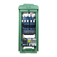
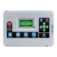
Details the parts of the Receiver unit including cover, antenna, indicators, and buttons.

Sensor;Transmitter Overview

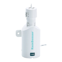
Details the parts of the Sensor/Transmitter unit including test spindle, adjustment cap, and mounting bracket.

Quick Start Installation Instructions

Wiring and Initial Testing

Connect Receiver power and control wires to the controller, then test wiring and operation.

Sensor;Transmitter Mounting and Adjustment

Adjust rainfall sensitivity and mount the Sensor/Transmitter in an unobstructed location.

Detailed Installation Instructions

Mounting the Receiver

Instructions for physically attaching the Receiver unit adjacent to the irrigation controller.

Receiver Control Wire Connection

Connects the Receiver's control wires to the irrigation controller's sensor or valve common terminals.

Receiver Power Wire Connection

Connects the Receiver's power wires to the 24V AC source on the irrigation controller or transformer.

Testing Procedures

Initial Receiver and Signal Testing

Verifies Receiver power, Sensor status, and signal strength at close range and installation site.

Rainfall Adjustment

Adjusts the Sensor/Transmitter sensitivity to trigger at specific rainfall amounts (1/8" to 1").

Sensor;Transmitter Installation Site Selection

Guidance on selecting an outdoor location for optimal rainfall exposure and signal reception.

Control System Operation Test

Confirms the RainSensor suspends watering when activated by the test spindle.

Sensor;Transmitter Mounting Procedure

RainSensor Operation Modes

Normal Operation

Describes how the system functions during rainfall and drying cycles.

Smart Bypass Function

Explains how to temporarily deactivate the RainSensor using the bypass button.

Power Down Mode

Details how to turn the Receiver OFF entirely using the Smart Bypass button.

Receiver Learn Mode

Procedure for pairing a new Sensor/Transmitter with the Receiver by changing its address code.

Attention Required Indicator

Explains the Power Indicator blinking and its meaning (low battery or communication issue).

Troubleshooting and Maintenance

Sensor;Transmitter Battery Replacement

Step-by-step guide to replacing the batteries in the Sensor/Transmitter unit.

Changing Sensor;Transmitter Code

Instructions on how to modify the transmission code to prevent unwanted activations.

Signal Indicator Validation

How to use the Signal Indicator for checking signal strength during installation.

Solving Reception Problems

Tips and explanations for resolving issues with wireless signal reception and range.

Electromagnetic Compatibility and Performance

Radio Frequency Performance Tips

Advice on antenna positioning, proximity to metal, and optimal placement for best RF performance.

Electromagnetic Compatibility

FCC compliance statement and instructions for resolving radio/TV interference.

FCC ID and IC Information

Provides the FCC ID and Industry Canada certification numbers for the device.

Specifications

Toro Limited One-Year Warranty

Related product manuals