g01 1947
Figure 60
1. Cover
2. Bolts
3. Thoroughly clean the inside of the cover and
the inner components of the clutch using
compressed air .
4. Install the clutch cover and secure it with the 3
bolts ( Figure 60 ) that you removed in 2 .
5. Lower the cargo bed.
Reducing the T op Speed
CAUTION
The dust in the clutch will become airborne
and could damage your eyes or you could
inhale it, causing breathing difculties.
W ear safety goggles and a dust mask or
other eye and respiratory protection when
performing this procedure.
1. Raise and latch the cargo bed; refer to Raising
the Cargo Bed ( page 20 ) .
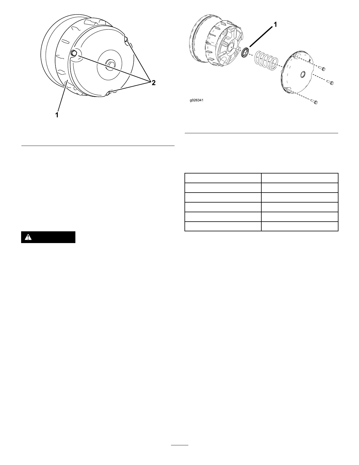
2. Remove the bolts securing the primary clutch
cover as shown in Figure 61 .
Important: Use caution when removing
the clutch cover; the spring is under
compression.
Important: T ake note of the X orientation
on the clutch covers and clutch assemblies
for later installation.
g026341
Figure 61
1. Clutch spacer
3. Remove the spring.
4. Add or remove spacers to adjust the top speed.
Use the following table to determine the amount
of spacers needed.
Spacers T op Speed
2 (standard) 16 mph (standard)
3 12 mph
4 9 mph
5
6 mph
6 4 mph
Important: Do not operate the machine
without at least 2 clutch spacers in place.
5. Install the spring and clutch cover .
Important: Ensure that the X is placed back
in the original location.
6. T orque the bolts to 179 to 228 N∙m (132 to 168
in-lb).
49