g033054
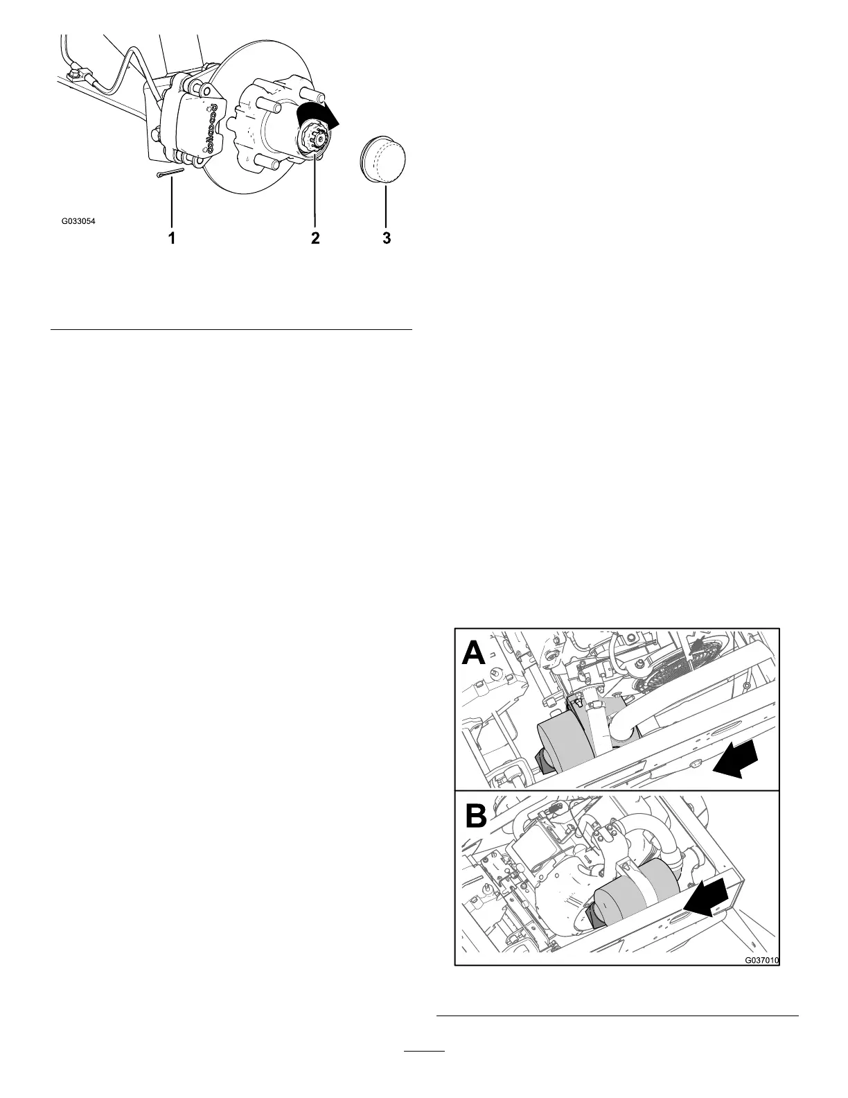
Figure 28
1. Cotter pin
3. Dust cap
2. Nut retainer
9. Install the cotter pin and bend each legs around
the retainer ( Figure 28 ).
10. Install the dust cap onto the hub ( Figure 28 ).
1 1. Repeat steps 1 through 10 for the hub and rotor
at the other side of the machine.
Installing the Brakes and Wheels
1. Clean the 2 ange-head bolts (3/8 x 3/4 inch) and
apply a coat of medium-strength thread-locking
compound to the threads of the bolts.
2. Align the brake pads to either side of the rotor
( Figure 23 ) and the holes in the caliper bracket
with the holes in the brake mount of the spindle
frame ( Figure 27 ).
3. Secure the caliper bracket to the spindle frame
( Figure 23 ) using the 2 ange-head bolts (3/8
x 3/4 inch).
T orque the 2 ange-head bolts to 47 to 54 N∙m
(35 to 40 ft-lb).
4. Align the holes in the wheel to the studs of the
hub and assemble the wheel to the hub with the
valve stem outward ( Figure 22 ).
Note: Ensure that the mounting surface of the
wheel is ush with the hub.
5. Secure the wheel to the hub using the lug nuts
( Figure 22 ).
T orque the lug nuts to 108 to 122 N∙m (80 to 90
ft-lb).
6. Repeat steps 1 through 5 for the brake and
wheel on the other side of the machine.
Engine Maintenance
Engine Safety
• Shut of f the engine, remove the key , and wait for
all moving parts to stop before checking the oil or
adding oil to the crankcase.
• Keep your hands, feet, face, clothing, and other
body parts away from the muf er and other hot
surfaces.
Servicing the Air Filter
Service Interval : Every 100 hours Replace the
air-lter element sooner if it dirty or
damaged.
Note: Service the air lter more frequently (every few
hours) if operating conditions are extremely dusty or
sandy .
Checking the Air Filter
1. Raise the cargo bed and secure it with the prop
rod.
2. Check the air-cleaner body for damage which
could possibly cause an air leak ( Figure 29 and
Figure 30 ).
Note: Ensure the cover seals around the
air-lter body .
Note: Replace a damaged air-lter cover or
housing.
g037010
Figure 29
33