Page 6
ITM-MAGMETER-T500-ED2
If the instrument has been disconnected from power supply for period longer than 6 months, the internal clock
battery can be empty. It is recommended to check time and date when putting the instrument in operation after
longer downtime.
The battery will be automatically charged after the instrument has been connected to power supply.
To ensure the proper function of the instrument, the measuring section of the induction fl ow meter sensor –
measuring tube – has to be completely fl ooded with the measured liquid and the measuring section cannot be
infl uenced by any disturbing elements as valves, pumps, bends or sharp deviations in the tubing section.
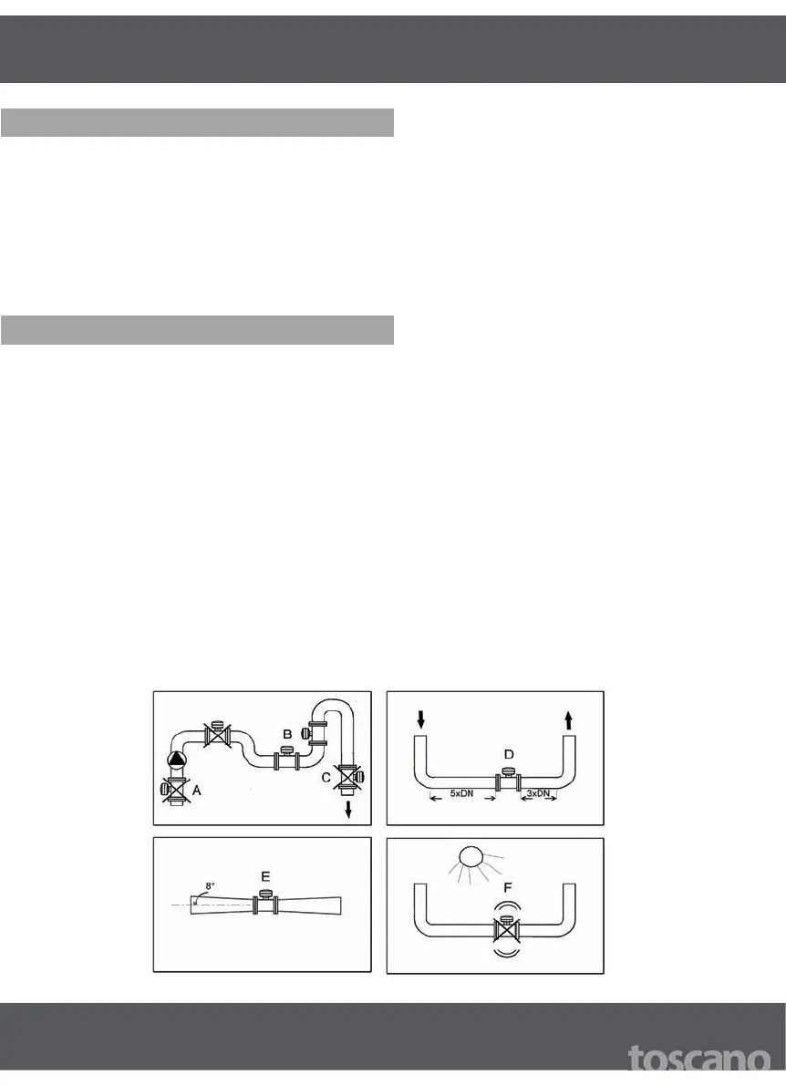
Therefore, observe the following instructions when installing the fl ow meter into the tubing:
If the system includes pumps, never place the fl ow meter sensor into the pump intake (A)! 1.
Place the fl ow meter sensor into the lowest point of the horizontal part of the tubing or into the ascendant 2.
tubing (B); never place the sensor into the tubing in the fl ow top-down direction (C)!
Ensure that steady (straight) parts of tubing are min. 5 x DN before the instrument and 3 x DN behind the 3.
instrument (D).
Tubing reductions with slope up to 8° are considered as straight (E). 4.
Prevent the instrument from being exposed to vibrations or direct sunlight (F). 5.
4. Important
5. Location