Do you have a question about the Toshiba e-STUDIO211 and is the answer not in the manual?
Guidelines for safely transporting and installing the equipment, including weight and clearance requirements.
Safety measures to be taken during service, including power handling, static electricity, and avoiding hazardous areas.
Identification of critical safety parts like breakers, fuses, and IC-RAMs that require careful handling.
Guidelines for safely transporting and installing the equipment, including weight and clearance requirements.
Safety measures to be taken during service, including power handling and avoiding hazardous areas.
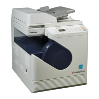
Detailed technical specifications of the e-STUDIO181/211, including copy process, type, and accepted originals.
A comprehensive list of error codes displayed by the equipment, including classification, contents, and troubleshooting steps.
Specific error codes related to paper jams, detailing the cause and relevant troubleshooting page.
Error codes indicating a service call is required, categorized by system and providing troubleshooting references.
Overview of self-diagnosis modes, including their purpose, operation procedure, and exit methods.
Procedure to check the status of input signals using the 'INTERRUPT' button and digital keys.
Procedure to check the status of output signals by keying in specific codes in Test Mode 04.
Procedure for printing embedded test patterns using specific codes in Test Print Mode 07.
Procedure for outputting lists of function settings, adjustment modes, and system settings.
Functionality for storing, deleting, and confirming access codes and counter values.
Method for setting function tables, consisting of 8 bits, to enable desired functions.
Overview of items available for correction or change within the Adjustment Mode (05).
Overview of configurable items within the Setting Mode (08), categorized by classification.
Procedures for checking the operation of various items like SRAM, DRAM, CODEC, ADF, buttons, and LEDs.
Procedure for setting the country/region code, primarily required after replacing the SRAM board.
Procedure for adjusting the auto-toner sensor after replacing the developer material.
Overview of image dimensional adjustment items and the recommended order for performing them.
Overview of image dimensional adjustment items and the recommended order for performing them.
Method for adjusting paper alignment at the registration roller using specific codes in Adjustment Mode 05.
Procedures for adjusting reproduction ratio and laser writing start position for the printer.
Procedures for adjusting reproduction ratio, image position, and margins for scanner output.
Procedure to adjust center density and density variation using density adjustment keys.
Method for adjusting the gamma slope angle, affecting contrast and image gradation.
Procedure to adjust image sharpness, allowing control over image clarity and moire reduction.
Switching background/text peak values between 'varied' and 'fixed' for range correction.
Setting the levels of the background peak for range correction to control background density.
Setting the levels of the text peak for range correction to adjust text density.
Procedure to adjust settings to improve smudged or faint text appearance in copied images.
Setting the image density level for copying, allowing adjustment for specific sub-codes.
Procedure to adjust settings that improve smudged or faint text in printed images.
Setting the image density level for printing, adjustable for standard and toner saving modes.
Procedure to adjust center density and density variation for scanned images.
Procedure to adjust scan image sharpness, controlling image clarity and reducing moire.
Switching background/text peak values between 'varied' and 'fixed' for range correction in scanning.
Setting background peak levels for range correction to control background density in scanned images.
Setting text peak levels for range correction to adjust text density in scanned images.
Procedure for adjusting high-voltage transformer outputs for main charger, developer bias, transfer, and separation chargers.
Precautions for developer bias and transfer/separation charger adjustments, including notes on blotched or poor transfer images.
Procedure for replacing and adjusting the CIS unit, including error recovery and control status checks.
Procedure for adjusting the tension of the CIS unit drive belt-1 during installation.
Procedure for adjusting the tension of the CIS unit drive belt-2 with a belt tension jig.
Procedure to adjust guides to correct sideways deviation of the printed image caused by paper feeding.
Procedure for adjusting the gap between the developer sleeve and doctor blade using a doctor-sleeve jig.
Procedure for adjusting the ADF position if it is not installed correctly, checking pin fitment.
Procedure for adjusting the ADF height by checking the gap between the platen guide and glass.
Procedure to adjust the aligning plate to correct image skew in the ADF output.
Procedure to adjust the leading edge position of the copied image from the ADF.
Procedure to adjust the horizontal position of the copy image by checking the center line.
Procedure to adjust the copy ratio of the ADF output by checking image dimension.
Procedure to adjust the bracket position for the ADF opening/closing sensor.
General descriptions for the preventive maintenance procedure, including timing and preparation steps.
List of operational items to check and replace during equipment overhauling based on usage or time.
Checklist for preventive maintenance tasks, including cleaning, lubrication, replacement cycles, and operation checks.
List of PM kits and their contents, including product name, part name, and quantity.
List of jigs required for preventive maintenance procedures, including their item name and page reference.
List of greases used for maintenance, including grease name, part name, volume, and container.
Precautions for storing toner, developer, drums, rollers, and paper to maintain their quality.
Detailed precautions for storing toner, developer, photoconductive drums, rollers, and paper.
Guidelines for handling, cleaning, and checking the photoconductive drum, including notes on patting powder and scratches.
Precautions and procedure for checking and cleaning the drum cleaning blade edge.
Procedures for checking and cleaning the fuser and pressure rollers, including notes on handling precautions.
Diagnostic steps and prescriptions for various error codes, guiding troubleshooting based on specific codes.
Troubleshooting steps for paper jams related to exit sensor and registration roller clutch issues.
Troubleshooting for bypass and drawer paper misfeeding, focusing on sensor and solenoid checks.
Troubleshooting for ADU, front, and PFU cover open jams, checking sensors and power supply.
Troubleshooting for ADF jams related to registration and read sensors, including checks for rollers and ADF boards.
Troubleshooting for main motor abnormalities, checking LEDs, connectors, and board connections.
Troubleshooting for CIS unit initialization errors and peak detection errors.
Troubleshooting for fuser thermistor/heater abnormalities, checking heaters, thermistors, and MAIN board.
Troubleshooting for polygonal motor abnormalities and H-Sync detection errors in the laser optical unit.
Troubleshooting for polygonal motor and H-Sync detection errors in the laser optical unit.
Troubleshooting for firmware update errors (C94) and high-voltage transformer abnormalities (C97).
Troubleshooting for ADF I/F errors (C55, F11) related to optional communication.
Troubleshooting steps for abnormalities in image density and gray balance, including adjustment procedures.
Troubleshooting steps for abnormalities in image density and gray balance, including adjustment procedures.
Identifying causes and solutions for background fogging, covering density, toner, and developer material.
Diagnosing and correcting moire patterns and lack of sharpness in images using density and processing parameters.
Troubleshooting toner offset issues, checking fuser roller, paper type, and developer material.
Troubleshooting for blurred images, checking paper dampness, scanner cleanliness, and ozone exhaust.
Diagnosing and resolving poor fusing issues by checking heater, pressure, temperature, and paper settings.
Troubleshooting steps for blank copies, checking transfer charger wire, high-voltage transformer, and developer unit.
Troubleshooting solid copy issues by checking exposure lamp, scanner, and main charger components.
Diagnosing white banding by checking laser optical unit, main charger, developer unit, and scanner.
Troubleshooting white banding by checking main charger, drum, developer unit, and drive systems.
Troubleshooting skewed images by checking drawers, rollers, CIS unit, and feed system alignment.
Diagnosing black banding by checking laser optical unit, main charger, developer unit, and scanner.
Troubleshooting black banding by checking main charger, fuser unit, drum, and scanner.
Identifying causes and solutions for white spots, covering developer unit, toner, main charger, and transformer.
Troubleshooting poor image transfer by checking paper, transfer charger, and registration roller.
Diagnosing uneven image density by checking main charger, transfer charger, discharge LED, and developer unit.
Troubleshooting faded images by checking toner, auto-toner circuit, developer material, and main charger.
Troubleshooting image dislocation by adjusting leading edge position, rollers, and clutch.
Diagnosing jittering images by checking toner, rollers, drum, carriage, and scanner units.
Troubleshooting poor cleaning by checking developer material, cleaner, toner recovery, and fuser unit.
Diagnosing uneven light distribution by checking original glass, main charger, discharge LED, and CIS unit.
Troubleshooting blotched images by checking paper type, separation charger, transfer charger, and transformer.
Procedure for replacing the MAIN board, including SRAM and expansion memory installation, and firmware update.
Procedure for replacing the SRAM board, including handling adjustment values and RAM clear.
Procedure for updating firmware automatically using a download jig and PC connection.
Detailed steps for updating firmware using the PWA-DWNLD-350-JIG, including connecting the jig and turning on power.
Procedure for writing data to the download jig using a ROM writer adapter and PC.
Procedure for updating firmware using the K-PWA-DLM-320 download jig to the ADF control PC board.
Step-by-step guide for updating firmware using the software update tool and a USB cable.
Description of the software update tool used for upgrading system ROM versions via a PC.
Lists the required systems and specifications for operating the software update tool.
Steps for confirming the USB driver and preparing for the software update tool installation.
Description of the output channels for the main switch line and cover switch line, indicating voltage and destination.
Table listing fuses by voltage, board/unit, part, and fuse type, to aid in troubleshooting blown fuses.
A schematic diagram illustrating the internal configuration and connections of the power supply unit.
A diagram showing the AC wire harness connections throughout the equipment.
A diagram illustrating the DC wire harness connections, detailing connections to various boards and components.
Diagrams showing the physical layout of electric parts, including motors, sensors, PC boards, and lamps.
| Functions | Print, Copy, Scan |
|---|---|
| Print Speed (Black) | 21 ppm |
| Print Resolution | 2400 x 600 dpi |
| Connectivity | USB 2.0 |
| Copy Speed (Black) | 21 cpm |
| Scanner Type | Flatbed |
| Weight | 46.3 lbs |
| Max Print Resolution (Black) | 2400 x 600 dpi |
| Max Paper Size | A3 |
| Copy Resolution | 600 x 600 dpi |
| Scan Resolution | 600 x 600 dpi |
| Interface | USB 2.0 |
| Warm-up Time | 25 seconds |
| Zoom | 25% to 400% |