Basic Installation and Operation Guide
JK Series 720 Controllers
TOSHIBA
Device/Mechanism Checks
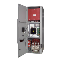
All devices should be checked for damage (Fig. 19). All necessary
repairs or replacements should be made.
Do not energize damaged equipment that
has not been repaired and verified.
Ensure that safety signs are not covered or obscured by paint.
Do not remove, cover, or destroy any
safety signs.
Fig. 19 Device/Mechanism Check
The setting of any adjustable current (e.g. motor overload protection relay) and voltage trip mechanisms should
be verified to the proper values.
NOTE:
Damage from faults can be reduced if devices used for short circuit and ground fault protection are
chosen and set to operate at values as close to minimum as feasible, while allowing normal
transients.
All switches, relays, and other operating mechanisms should be manually exercised to make certain that they are
properly aligned and operate freely.
Operating mechanisms such as interlocks, key switches, etc. should be checked for function as intended for
protection of personnel and equipment.
The motor/load protection relay should be checked to be sure that proper
settings have been programmed per the motor/load specification sheet and
nameplate data (Fig. 20). Check the instruction manual for the specific relay
supplied with your equipment for factory default settings and additional
protection and programming details
NOTE:
Factory settings are per the information provided by the
customer. If not provided, factory settings include CT & PT
ratio, estimated motor/load FLA. Settings like motor service
factor and overload class will be minimum (e.g. 1.0 S.F,
Class 10 OL curve) which may cause a nuisance trip during
the initial start unless adjusted for the application. Most
settings are disabled and many should be turned on at the
end of commissioning.
Fig. 20 Protection Relay Setting
Check
Power circuit fuses were selected and installed in accordance with the application requirements. Confirm the proper
fuses were provided. The fuses must be completely inserted in their holders. Instructions on removing and installing
the fuses can be found in this manual on page 29.
 Loading...


