–21–
Outdoor Unit
Installation Manual
Outdoor Unit
Installation Manual
4 The 7-segment display indicates .
After the indication, starts flashing on the display.
When the flashing stops and remain lit on the display, the setting is
complete.
Interface P.C. board on the outdoor unit
• When 2 or more refrigerant lines are controlled as a group, be sure to turn on all the indoor units in the group
before setting addresses.
• If you set the unit addresses of each line separately, each line’s header indoor unit is set separately. In that case,
the CODE No. “L03” (indoor header unit overlap) is indicated as running starts. Change the group address to
make one unit the header unit using wired remote controller.
◆ Address setting procedure 2
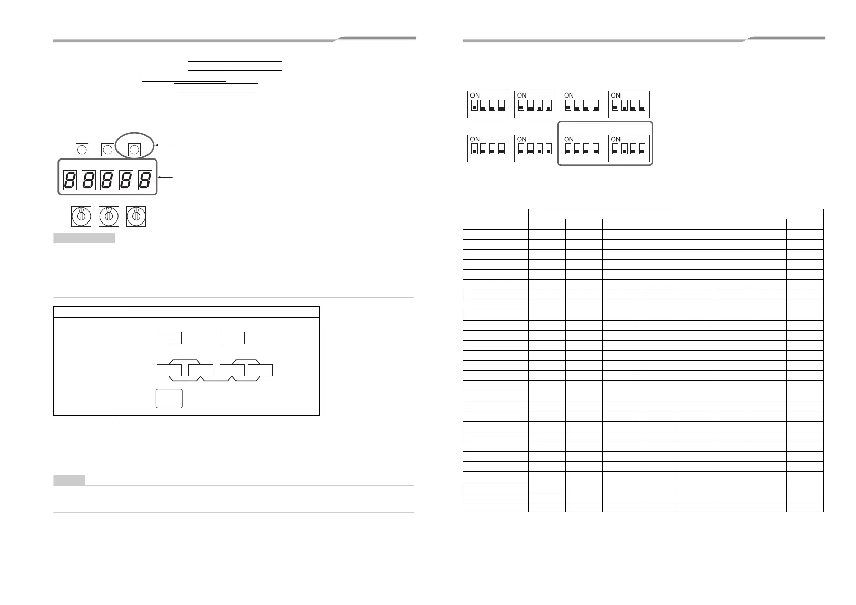
1 Set a system address for each system using SW 13 and 14 on the interface P.C. board on the
outdoor unit of each system.
(factory default: Address 1)
Be sure to set a unique address on each system. Do not use a same address as another system (refrigerant line)
or a custom side.
(Example) Controlling 2 or more refrigerant lines as a group
System wiring
diagram
U. 1. - - - (U. 1. flash)
U. 1. - - - (U. 1. light)
SW04
SW05 SW15
SW01
SW02 SW03
D600 D601 D602 D603
D604
Outdoor
Indoor
Indoor
Indoor
Indoor
Outdoor
Remote
controller
(Group control)
Interface P.C. board on the outdoor unit
Switch settings for a line (system) address on the interface P.C. board on the outdoor unit
(: switch ON, ✕: switch OFF)
“–”: not used for system address setting (Do not change their positions.)
Line (system) address
SW13 SW14
12341234
1 –––✕✕✕✕✕
2 –––✕ ✕✕✕
3 –––✕✕ ✕✕
4 –––✕ ✕✕
5 –––✕✕✕ ✕
6 –––✕ ✕ ✕
7 –––✕✕✕
8 –––✕ ✕
9 –––✕✕✕✕
10 –––✕ ✕✕
11 –––✕✕ ✕
12 –––✕ ✕
13 –––✕✕✕
14 –––✕ ✕
15 –––✕✕
16 –––✕
17 ––– ✕✕✕✕
18 ––– ✕✕✕
19 ––– ✕ ✕✕
20 –––✕✕
21 ––– ✕✕ ✕
22 ––– ✕ ✕
23 ––– ✕ ✕
24 –––✕
25 –––
✕✕✕
26 ––– ✕✕
27 ––– ✕ ✕
28 –––✕
SW06 SW07 SW09 SW10
SW11 SW12 SW13 SW14
1234 1234 1234 1234
1234 1234 1234 1234
41-EN 42-EN
+00EH99883601_00Ta.book Page 21 Thursday, September 8, 2011 4:34 PM