–3–
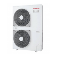
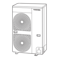
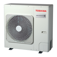
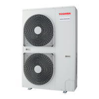
Outdoor Unit
Installation Manual
Outdoor Unit
Installation Manual
2 Accessory parts
• Before installing the unit, check that the unit has the correct model name to prevent the wrong unit from being installed
in the wrong place.
• Before proceeding to weld the refrigerant pipe, be sure to pass nitrogen through the pipe.
• Before installing the indoor units, read the instructions in the installation manual provided with the indoor units.
• Before installing a branch pipe, read the instructions in the installation manual provided with the branch pipe kit.
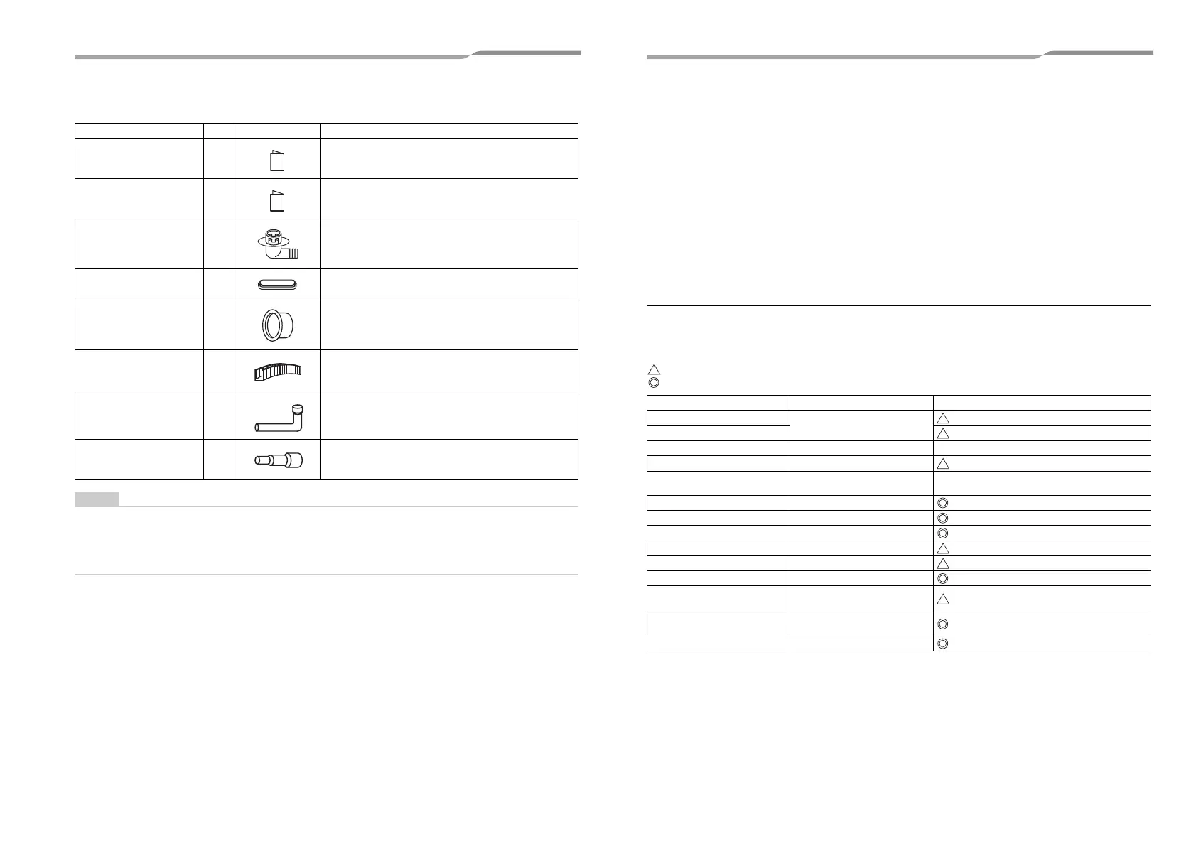
Part name Q’ty Shape Usage
Owner’s Manual 1 Hand this directly to the customer.
Installation Manual 1 Hand this directly to the customer.
Drain nipple 1
Waterproof rubber cap 1
Protective bush 1 For protecting wires (pipe cover)
Guard material for passage
part
1 For protecting passage part (pipe cover)
Joint pipe (Ø19.1 - Ø22.2) 1
For the pipe inside the outdoor unit (MCY-MAP0804HT8 / HT7
only)
Joint socket (Ø15.9 - Ø22.2) 1
For the pipe inside the outdoor unit (MCY-MAP0804HT8 / HT7
only)
3 Installation of new refrigerant air
conditioner
This air conditioner adopts the new HFC refrigerant (R410A) which does not deplete the ozone layer.
• R410A refrigerant is vulnerable to impurities such as water, oxidizing membranes, or oils because the pressure
of R410A refrigerant is higher than that of the former refrigerant by approximately 1.6 times.
As well as the adoption of the new refrigerant, the refrigerating oil has been also changed. Therefore, pay
attention so that water, dust, former refrigerant, or refrigerating oil does not enter the refrigerating cycle of the
new refrigerant air conditioner during installation.
• To prevent mixing of refrigerant or refrigerating oil, the size of the charge port of the main unit or connecting
section of the installation tool differs to that of an air conditioner for the former refrigerant.
Accordingly, exclusive tools are required for the new refrigerant (R410A) as shown below.
• For connecting pipes, use new and clean piping materials so that water or dust does not enter.
Required tools and cautions on handling
It is necessary to prepare the tools and parts for installation as described below. The tools and parts which will be
newly prepared in the following items should be restricted to exclusive use.
Explanation of symbols
: Newly prepared (It is necessary to use it exclusively with R410A, separately from those for R22 or R407C.)
: Former tool is available.
Used tools Usage Proper use of tools / parts
Gauge manifold
Vacuuming, charging refrigerant
and operation check
Exclusive to R410A
Charging hose Exclusive to R410A
Charging cylinder Charging refrigerant Unusable (Use the Refrigerant charging balance.)
Gas leak detector Checking gas leak Exclusive to R410A
Vacuum pump Vacuum drying
Usable if a counter-flow preventive adapter is
attached
Vacuum pump with counterflow Vacuum drying R22 (Existing article)
Flare tool Flare processing of pipes Usable by adjusting size
Bender Bending processing of pipes R22 (Existing article)
Refrigerant recovery device Recovering refrigerant Exclusive to R410A
Torque wrench Tightening flare nut Exclusive to Ø12.7 mm and Ø15.9 mm
Pipe cutter Cutting pipes R22 (Existing article)
Refrigerant canister Charging refrigerant
Exclusive to R410A
Enter the refrigerate name for identification
Welding machine / Nitrogen gas
cylinder
Welding of pipes R22 (Existing article)
Refrigerant charging balance Charging refrigerant R22 (Existing article)
5-EN 6-EN
+00EH99883601_00Ta.book Page 3 Thursday, September 8, 2011 4:34 PM