–8–
Outdoor Unit
Installation Manual
EN
Outdoor Unit
Installation Manual
Optional installation parts (locally procured)
Follow the instructions in the installation manual provided with the branch pipe kit and the instructions in the installation
manual of the indoor unit to connect the refrigerant pipe between the branch pipe and indoor unit.
Refrigerant piping connection
Take note of these 4 important points below for piping work
1. Keep dust and moisture away from inside the connecting pipes.
2. Tightly connect the connection between pipes and the unit.
3. Evacuate the air in the connecting pipes using a VACUUM PUMP.
4. Check for gas leaks at connection points.
Flaring
1. Cut the pipe with a pipe cutter.
2. Remove the burr inside of the pipe.
When removing the burr, be careful so that chips do not fall into the pipe.
3. Remove the flare nuts attached to the outdoor / indoor unit, then insert them into each of the pipes.
4. Flare the pipes.
See the following table for the projection margin (A) and flaring size (B).
* In case of flaring for R410A with the conventional flare tool, pull the tool out approx. 0.5 mm more than that for
R22 to adjust it to the specified flare size.
The copper pipe gauge is useful for adjusting the projection margin size.
Parts name Q’ty
A
Refrigerant piping
Liquid side: Ø9.5 mm
Gas side: Ø19.1 mm and Ø22.2 mm
One each
B
Pipe insulating material
(polyethylene foam, 10 mm thick)
1
C Putty, PVC tape One each
Pipe A B Flare Nut
Outside
diameter
Thickness
Rigid
(clutch type)
R410A tool
Imperial
(wing nut type)
R410A tool
Width across
flat
Tighten torque
mm mm mm mm mm mm N•m kgf•m
9.5 0.8 0 to 0.5 1.0 to 1.5 13.2 22 33 to 42 3.3 to 4.2
19.1 1.2 0 to 0.5 1.0 to 1.5 24.0 36 100 to 120 10.0 to 12.0
Obliquity
Roughness
Warp
90°
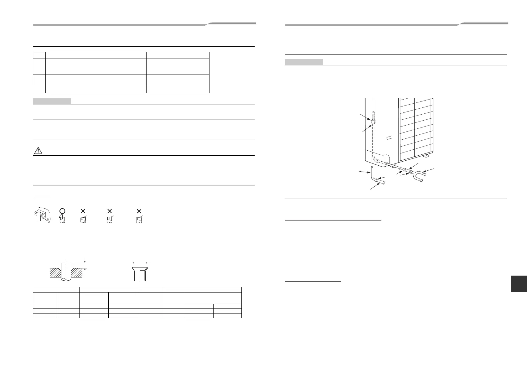
Connecting the pipe at the gas side (MCY-MAP0804HT8 / HT7
only)
• Connecting the main pipe (Ø19.1) directly to the gas valve (Ø19.1) may lower the performance.
• To connect the main pipe (Ø22.2) to the gas valve (Ø19.1), use the joint pipe (Ø19.1 - Ø22.2) and joint socket (Ø15.9
- Ø22.2) that come with the outdoor unit.
• Before welding the refrigerant pipe, be sure to pass nitrogen through the pipe to prevent oxidation inside the pipes.
Failure to observe this precaution may cause the refrigerant pipe to become clogged due to oxidation scale.
◆ Connection procedure
To connect at the front, sides, or back
1 Braze the supplied joint pipe to the main pipe (Ø22.2).
2 Remove the nut from the valve at the gas side, insert the nut into the supplied joint pipe, then flare
the tip of the pipe.
3 Tighten the supplied joint pipe to the valve at the gas side using a nut by the specified torque in
the same direction as removing the outdoor unit pipe.
4 Connect and braze the supplied joint socket between the main pipe (Ø22.2) and branch pipe
(Ø15.9).
To connect downward
1 Cut the supplied joint pipe, then braze the main pipe (Ø22.2).
2 Remove the nut from the valve at the gas side, insert the nut into the supplied joint pipe, then flare
the tip of the pipe.
3 Tighten the supplied joint pipe to the valve at the gas side using a nut by the specified torque.
4 Connect and braze the supplied joint socket between the main pipe (Ø22.2) and branch pipe
(Ø15.9).
Joint pipe (L-shape, supplied)
Solder
Joint socket (straight, supplied)
Branch pipe
Ø22.2 pipe (locally procured)
Flare connection
Gas side ball valve Ø19.1
15-EN 16-EN
+00EH99883601_00Ta.book Page 8 Thursday, September 8, 2011 4:34 PM