–29–
Outdoor Unit
Installation Manual
Outdoor Unit
Installation Manual
▼ Finishing operation
1 Set the rotary switches on the interface P.C. board of the outdoor unit back: SW01 to [1], SW02 to
[1] and SW03 to [1].
<Corrective test run>
▼ Start operation
1 Set the rotary switches on the interface P.C. board of the outdoor unit as below.
When in “COOL” mode: SW01=[2], SW02=[5], SW03=[1].
When in “HEAT” mode: SW01=[2], SW02=[6], SW03=[1].
2 Push and hold SW04 for more than 2 seconds.
• You cannot change the temperature setting during the test run.
• Errors are detected as usual.
• The unit does not perform test run for 3 minutes after turning the power on or stopping running.
[A]
[U1]
[B]
[ ]
7-segment display
[A]
[C ]
[H ]
[B]
[ ]
[ ]
7-segment display
[A]
[C ]
[H ]
[B]
[ - C ]
[ - H ]
7-segment display
▼ Stop operation
1 Set the rotary switches on the interface P.C. board of the outdoor unit back:
SW01 to [1], SW02 to [1] and SW03 to [1].
[A]
[U1]
[B]
[ ]
7-segment display
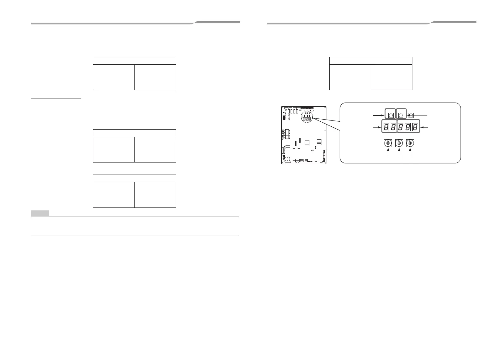
SW04
SW01 SW02
SW03
D600 D601 D602 D603 D604
SW05 SW15
Push switch
7-segment
display [A]
Push switch
7-segment
display [B]
Rotary switches
Interface PC board
57-EN 58-EN
+00EH99883601_00Ta.book Page 29 Thursday, September 8, 2011 4:34 PM