ter
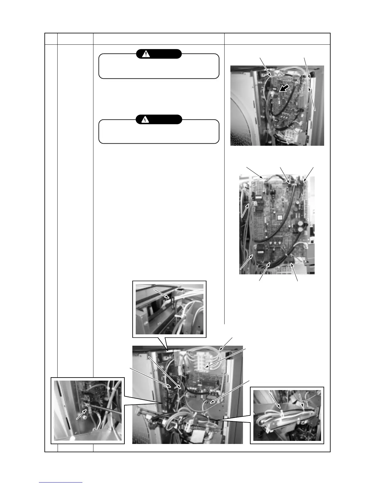
I/F P.C. board
Supporter
Solenoid
valve coil
Compressor lead
U : CN09 → Red
V : CN10 → White
W : CN11 → Black
Fan motor (down)
connector
High pressure SW
connector
No.
2
Part name
Inverter
assembly
Procedure
CAUTION
Wear protective clothing on your hands as
other components may cause injury etc.
<Disassembling>
1) Stop the unit operation and turn off the power
supply to the unit.
WARNING
Never open the cabinet while five minutes
after turn off the power supply.
2) Remove front and upper cabinet.
(Screw Ø4 × 10 9 pcs)
3) Remove power supply and remote controller
wires. (Screw of terminal block)
4) Remove wires to I/F P.C. board.
(Solenoid valve coil, 4-way valve coil, heater,
comp thermo, PMV coil, sensor)
5) Open I/F P.C. board on the slant.
(Screw Ø4 × 8 2 pcs and supporter)
6) Remove the reactor wires.
(Screw of terminal block, wire clamp and
bundle band)
7) Remove wires of sensors and PMV coil.
(Wire clamp and bundle band)
8) Remove fan motors lead wires. (Two points)
9) Remove IPDU wires.
(Compressor lead wires and high pressure SW
wires)
Remarks
 Loading...