– 10 –
FILE NO. SVM-07021
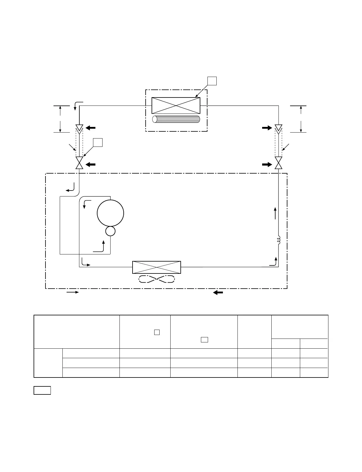
5. REFRIGERATION CYCLE DIAGRAM
5-1. RAS-07SKSX / RAS-07S2AX
Note
• Measure the heat exchanger temperature at the center of U-bend. (By means of TC sensor)
Ambient temp.
conditions DB/WB
(°C)
Indoor Outdoor
Standard 0.57 13.0 High 27/19 35/24
Cooling Overload 0.68 17.5 High 32/23 43/26
Low temperature 0.42 4.0 Low 21/15 21/15
Standard
pressure
P
(MPaG)
Surface temp. of heat
exchanger interchanging
pipe
T1
(°C)
Fan speed
(indoor)
50Hz
Heat exchanger
Indoor unit
Cross flow fan
Cooling
Cooling
Compressor
Heat e
xchanger
Propeller fan
Outdoor unit
Capillary tube
∅1.2x
50
0s
PH108X1C-4DZD
N2
Cooling
Mark ( ) means check points of Gas Leak.
O.D.:9.52mm O.D.:6.35mm
Cooling
Packed valve
(∅9.52)
Packed valve
(∅6.35)
0.39m
(Connecting pipe)
∅9.52
0.49m
(Connecting pipe)
∅6.35
T1
P
Refrigerant
R22 : 0.
58 kg.
 Loading...