Installation Place
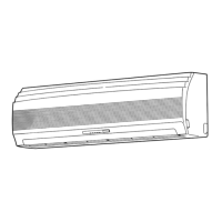
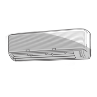
•Aplacewhichprovidesthespacesaroundtheindoorunitasshowninthe
diagram
•Aplacewheretherearenoobstaclesneartheairinletandoutlet
•Aplacewhichallowseasyinstallationofthepipingtotheoutdoorunit
•Aplacewhichallowsthefrontpaneltobeopened
•Theindoorunitshallbeinstalledatleast2.5mheight.Also,itmustbe
avoidedtoputanythingonthetopoftheindoorunit.
•Directsunlighttotheindoorunit’swirelessreceivershouldbeavoided.
•ThemicroprocessorintheindoorunitshouldnotbetooclosetoRF
noisesources.
(Fordetails,seetheowner’smanual.)
Remote control
•Aplacewheretherearenoobstaclessuchasacurtainthatmayblockthe
signalfromtheindoorunit
•Donotinstalltheremotecontrolinaplaceexposedtodirectsunlightor
closetoaheatingsourcesuchasastove.
•Keeptheremotecontrolatleast1mapartfromthenearestTVsetor
stereoequipment.(Thisisnecessarytopreventimagedisturbancesor
noiseinterference.)
•Thelocationoftheremotecontrolshouldbedeterminedasshownbelow.
(Side view) (Top view)
Indoor unit
Reception
range
Reception range
Remote
control
Remote
control
75°
45°
45°
Cutting a Hole and Mounting
Installation Plate
Cutting a hole
Wheninstallingtherefrigerantpipesfromtherear
The center of the pipe hole
is above the arrow.
Pipe hole
Ø65 mm
120 mm
1.Afterdeterminingthepipeholepositiononthemountingplate( ),drillthe
pipehole(Ø65mm)ataslightdownwardslanttotheoutdoorside.
•Whendrillingawallthatcontainsametallath,wirelathormetalplate,be
suretouseapipeholebrimringsoldseparately.
Mounting the installation plate
Hook
Pipe hole
Indoor unit
Hook
Hook
Thread
Weight
5
Mounting screw
Pipe hole
Installation
plate
300
144
50
65
103
300
50
1
When the installation plate is directly mounted
on the wall
1.Securelyfittheinstallationplateontothewallbyscrewingitintheupper
andlowerpartstohookuptheindoorunit.
2.Tomounttheinstallationplateonaconcretewallwithanchorbolts,use
theanchorboltholesasillustratedinthebelowfigure.
3.Installtheinstallationplatehorizontallyinthewall.
Wheninstallingtheinstallationplatewithamountingscrew,donotuse
theanchorboltholes.Otherwise,theunitmayfalldownandresultin
personalinjuryandpropertydamage.
5
Installation plate
(Keep horizontal direction.)
5 mm dia. hole
Clip anchor
(local parts)
Mounting screw
Ø4 mm x 25 ℓ
Anchor bolt
Projection
15 mm or less
Failuretofirmlyinstalltheunitmayresultinpersonalinjuryandproperty
damageiftheunitfalls.
•Incaseofblock,brick,concreteorsimilartypewalls,make5mmdia.
holesinthewall.
•Insertclipanchorsforappropriatemountingscrews
5
.
•Securefourcornersandlowerpartsoftheinstallationplatewith4to6
mountingscrewstoinstallit.
Piping and Drain Hose Installation
Piping and drain hose forming
*Sincedewingresultsinamachinetrouble,makesuretoinsulateboth
connectingpipes.(Usepolyethylenefoamasinsulatingmaterial.)
Rear right
Bottom right
Right
Rear left
Bottom left
Left
Changing
drain hose
Die-cutting
back body slit
1. Die-cutting back body slit
Cutouttheslitontheleftorrightsideofthebackbodyfortheleftorright
connectionandtheslitonthebottomleftorrightsideofthebackbodyfor
thebottomleftorrightconnectionwithapairofnippers.
2. Changing drain hose
Forleftwardconnection,bottom-leftwardconnectionandrearleftward
connection’spiping,itisnecessarytochangethedrainhoseanddrain
cap.
6
1122950109_S04_182x257_52p_S_p70_181217_EN+TR+RU.indd 8 12/25/2018 10:46:52 AM

 Loading...
