Do you have a question about the Toshiba RAS-24N3KV2-A and is the answer not in the manual?
| Brand | Toshiba |
|---|---|
| Model | RAS-24N3KV2-A |
| Category | Air Conditioner |
| Language | English |
General safety guidelines and symbol meanings before installation.
Specifications for power supply cords for general public use appliances.
Safety guidelines for installing AC using R410A refrigerant.
Critical safety warnings and dangers associated with installation and use.
General caution statements regarding installation and handling.
Safety precautions for handling R410A during installation and servicing.
Guidelines for installing refrigerant piping, including materials and joints.
Details on copper pipes and joints suitable for R410A.
Specifications and requirements for copper pipes used with R410A.
Information on flare and socket joints for R410A piping.
Procedures and precautions for cutting and flaring pipes.
Steps and safety measures for flare processing of pipes.
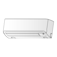
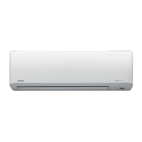
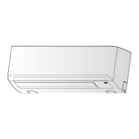
Detailed diagrams and dimensions of the indoor unit.
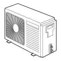
Detailed diagrams and dimensions of the outdoor unit.
Electrical wiring schematic for the indoor unit.
Electrical wiring schematic for the outdoor unit.
List and specifications of electrical components in the indoor unit.
List and specifications of electrical components in the outdoor unit.
Schematic illustrating the refrigerant flow within the air conditioner system.
Performance data under specific cooling and heating conditions.
Diagram showing control functions and signal flow for the indoor unit.
Diagram showing control functions and signal flow for the outdoor unit.
Overview of the air conditioner's control system and components.
Explains various operation modes and functions like cooling, heating, AUTO, DRY.
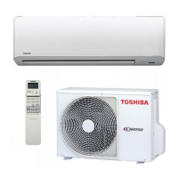
Visual guide for positioning indoor and outdoor units during installation.
Lists optional parts and required tools for installation.
Guidelines for selecting the installation place and drilling for the indoor unit.
Instructions for connecting electrical wiring between units and remote control.
Procedures for installing refrigerant piping and drain hoses.
Guidelines for outdoor unit placement and cold weather installation.
Steps for connecting refrigerant pipes, including flaring and tightening.
Procedure for evacuating the system using a vacuum pump.
Instructions and warnings for performing electrical wiring.
Common installation problems and their solutions.
Procedures for remote control selection, testing, and auto-restart setup.
Basic checks for power supply, voltage, and normal operation status.
Interpreting flashing LEDs on the indoor unit for self-diagnosis.
Using the remote controller service mode to diagnose errors via check codes.
Step-by-step guide for diagnosing issues based on observed symptoms.
Identifying and resolving issues related to interconnecting and serial signal wiring.
Detailed troubleshooting for specific error codes (e.g., F04, F06, F07).
Procedures for checking main parts like P.C. boards and motors.
Method to check if the outdoor fan motor is functioning correctly.
Step-by-step guide to replace components of the indoor unit.
Procedures for replacing parts of the outdoor unit.
Illustrated breakdown of indoor unit components with part numbers.
Illustrated breakdown of outdoor unit components with part numbers.