Do you have a question about the Toshiba RAS-24UK-AR and is the answer not in the manual?
| Brand | Toshiba |
|---|---|
| Model | RAS-24UK-AR |
| Category | Air Conditioner |
| Language | English |
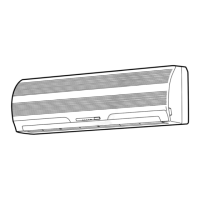
Detailed diagrams and dimensions for the indoor unit.
Detailed diagrams and dimensions for the indoor unit.
Detailed diagrams and dimensions for the outdoor unit.
Detailed diagrams and dimensions for the outdoor unit.
Electrical wiring diagram for specific models.
Electrical wiring diagram for specific models.
List and specifications of indoor unit electrical components.
List and specifications of outdoor unit electrical components.
List and specifications of outdoor unit electrical components.
Diagram illustrating the refrigeration cycle for specific models.
Diagram illustrating the refrigeration cycle for specific models.
Diagram illustrating the refrigeration cycle for specific models.
Block diagram showing the control flow of the air conditioner system.
Explains the roles of indoor and outdoor unit controllers.
Details the operation circuits for different modes.
Describes the quiet and mild operation mode.
Prevents excessive refrigerating cycle pressure.
Prevents indoor heat exchanger from freezing.
Allows automatic restart after power interruption.
Indicates when filter cleaning is required.
Essential safety precautions for installation.
Visual guide for unit placement and piping connection.
Covers optional parts and accessories for installation.
Specific steps for installing the indoor unit.
Specific steps for installing the outdoor unit.
Includes gas leak test and auto restart setting.
General steps for diagnosing issues.
Initial checks for power, wiring, and program control.
Interpreting self-diagnosis and initial fault indications.
Using the remote control to identify error codes.
Flowcharts for diagnosing specific component failures.
Specific troubleshooting steps for indoor unit issues.
Diagnosing issues related to interconnect and signal wiring.
Procedures for checking and troubleshooting the PC board.
Diagram showing the layout of components on the PC board.
Procedures for replacing indoor unit components.
Procedures for replacing outdoor unit components.
Procedures for replacing outdoor unit components.
Exploded diagram and parts list for the indoor unit.
Exploded diagram and parts list for the indoor unit.
Exploded diagram and parts list for the outdoor unit.
Exploded diagram and parts list for the outdoor unit.
Exploded diagram and parts list for the outdoor unit.