8
1. Remove cover of remote controller by sliding down and take it out.
2. If batteries are exist, please take them out. The combination of using
wire controller and batteries may cause of batteries explosion.
3. Make hole for insert control wire by use screwdriver break the plastic for
cover hole as shown on fi gure 4.
4. Insert control wire from rear side of remote controller as shown on
fi gure 5.
5. Fix control wire which arrange as shown on fi gure 6 and 7 to terminal
by provided screws (tighten fi rmly but not over 0.25 N·m (0.03 kgf·m)).
6. Set control wire through gutter way at rear side of remote controller as
shown on fi gure 8.
7. Fix provided screw (Ø3.1×16L) on the wall to hang remote controller as
shown on fi gure 9.
8. Mark and arrange hole for fi x below screw (Ø3.1×25L) as shown on
fi gure 9.
9. Assembly battery cover which provided with accessory bag then use
provide screw (Ø3.1×25L) to fi x battery cover together with wall as
shown on fi gure ! (tighten fi rmly but not over 0.15 N·m (0.02 kgf·m)).
10. Reassembly cover of remote controller.
45
Plastic for cover hole
Control wire
6
7
Control wire
Terminal
* Wire size 28-22AWG
or 0.08-0.32 mm
2
Outer diameter not over 4.7 mm,
control wire length 30 m. or less.
30 mm
10 mm
* Terminals for wiring can be either on right (type A) or left (type B), depending
on the controller packed in carton.
Type A Type B
Control wire
Hole for hang remote
controller
Remote controller
Control wire
Screw (Ø3.1×16L)
for hang remote
controller
Wall
Screw (Ø3.1×25L)
for fi x battery cover
Remote controller
89
!
Battery cover
Screw
Tighten fi rmly but not over
0.15 N·m (0.02 kgf·m)
Type A Type B
For remote controller
1. Securely remove two screws at the front panel.
Type A : Open the air inlet grille upward.
Type B : Open two screw caps.
2. Slightly open the lower part of the front panel then pull the upper part of
the front panel toward you to remove it as shown on fi gure 1.
3. Arrange the control wire as detail and specifi cation as shown on fi gure
2.
4. Securely connect the control wire to terminal of Display unit as shown on
fi gure 3 (tighten fi rmly but not over 0.12 N·m (0.01 kgf·m)).
5. Set the control wire out from indoor unit same portion as power supply
and connecting cable as shown on fi gure 3. (Notch for wire out)
6. Reassembly the indoor unit by reverse process of 1 to 2.
ScrewScrew
Front panel
1
Type : A
Screw
Screw cap
Screw
Front panel
1
Type : B
2
3
* Wire size 28-22AWG
or 0.08-0.32 mm
2
Outer diameter not over 4.7 mm,
control wire length 30 m. or less.
70 mm
5 mm
Terminal
Control wire
Notch for wire out
Control wire
Display unit
Indoor unit
Control wire
Remote controller
How to Connect Remote Controller
for Wire Operation
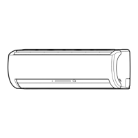
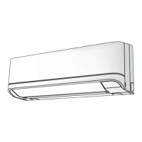
For indoor unit
 Loading...