8. CONTROL BLOCK DIAGRAM
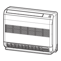
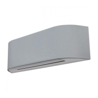
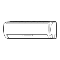
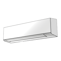
8-1. Indoor Unit
M.C.U.
Indoor Unit Control Unit
Serial Signal Communication
(Operation Command and Information)
Serial Signal Transmitter/Receiver
Converter
(D.C circuit)
Noise Filter
Indoor
Fan Motor
Louver
Motor
Louver Motor
Drive Control
Indoor Fan
Motor Control
Initializing Circuit
Clock Frequency
Oscillator Circuit
Power Supply
Circuit
Infrared Rays, 36.7kHz
Fan Speed Selection
ON TIMER Setting
OFF TIMER Setting
Louver AUTO Swing
Louver Direction Setting
REMOTE CONTROL
FLOOR (ON/OFF)
ECO
Heat Exchanger Sensor (TC)
Room Temperature Sensor (TA)
Infrared Rays Signal Receiver
and Indication
Functions
• Cold draft preventing Function
• 3-minute Delay at Restart for Compressor
• Fan Motor Starting Control
•
Processing
(Temperature Processing)
•
Timer / Weekly Timer
• Serial Signal Communication
• Clean Function
Heat Exchanger Sensor (TCJ)
Power Supply
From Outdoor Unit
Damper
Drive Control
Damper
Motor
•
Power Selection
Hi-POWER
COMPORT SLEEP
Remote Control
Operation (START/STOP)
Operation Mode Selection
AUTO, COOL, DRY, HEAT
Thermo. Setting

 Loading...