– 66 –
Shield pipe
Air filter
Hook
Hook
(Attach to the front panel)
2
Wireless remote
control
65 mm or more
170 mm
or more
170
mm
or more
1
Installation
plate
6
Bioenzyme filter
5
Zeolite filter
4
Remote control holder
For the rear left and left piping
Wall
Insert the cushion between
the indoor unit and wall,
and tilt the indoor unit for better
operation.
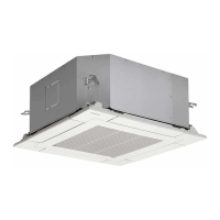
RAS-M10UKV-E3,RAS-M13UKV-E3,RAS-M16UKV-E3
Before installing the wireless
remote control
• With the remote control cover
open, load the batteries supplied
correctly, observing their
polarity.
2 Wireless remote control
3 Batteries
Cover
The auxiliary piping can be
connected the left, rear left,
rear right, right, bottom right or
bottom left.
Left
Rear left
Right
Rear right
Bottom right
Bottom left
Do not allow the drain hose to
get slack.
Cut the piping hole
sloped slightly
Make sure to run the drain hose
sloped downward.
8
Flat head wood screw
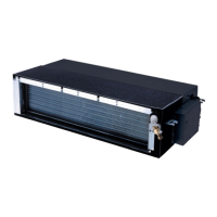
RAS-M10UKCV-E3,RAS-M13UKCV-E3,RAS-M16UKCV-E3
9-2. Indoor unit
Insulate the refrigerant
pipes separately with insulation,
not together.
6 mm thick heat resisting
polyethylene foam
Part name (Q'ty)
Mounting screw ∅4 x 25 s x 6
Flat head wood screw ∅3.1 x 16 s x 2
B Label x 1
Part
No.
1
2
3
Part name (Q'ty)
Installation plate x 1
Wireless remote control x 1
Battery x 2
Part name (Q'ty)
Remote control holder x 1
Zeolite filter x 1
Bioenzyme filter x 1
This model is not equipped with an extension drain hose.
Option :
For the extension drain hose, use an optionally available
RB-821SW or commercially available one.
Name
Owner's manual
Installation manual
Others
Part
No.
4
5
6
Part
No.
7
8
9
9-2-1. Accessory and Installation Parts
B

 Loading...