– 10 –
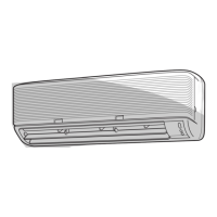
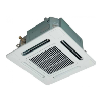
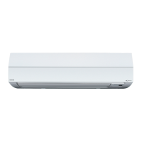
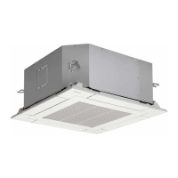
INDOOR UNIT
Evaporator
Allowable height difference
Allowable pipe length
Connecting pipe
Thickness : 0.8mm
Ø6.35
NOTE : Gas leak check position
Refrigerant flow (Cooling)
Refrigerant flow (Heating
*
1)
*
1 : Heat pump model only
Connecting pipe
Thickness : 0.8mm
Ø9.52
Sectional shape
of heat insulator
OUTDOOR UNIT
TA
Multi-blade fan
INDOOR UNIT
Evaporator
Allowable height difference
Allowable pipe length
Connecting pipe
Thickness : 0.8mm
Ø6.35
Connecting pipe
Thickness : 0.8mm
Ø12.7
Sectional shape
of heat insulator
OUTDOOR UNIT
TA
Multi-blade fan
•
•
TC
TC
6. REFRIGERANT CYCLE DIAGRAM
RAS-M10YDV-E, RAS-M10YDCV-E
RAS-M13YDV-E, RAS-M13YDCV-E
RAS-M16YDV-E, RAS-M16YDCV-E
• The allowable pipe length, charge amount of refrigerant, and allowable height difference differ according to the
outdoor unit to be combined.
For details, refer to the service manual of the outdoor unit to be combined.
 Loading...