– 21 –
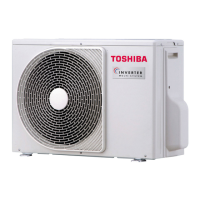
4-2. Outdoor Unit
RAS-M14GAV-E, RAS-M18GAV-E (Heat pump models)
RAS-M14GACV-E, RAS-M18GACV-E (Cooling only models)
2-Ø20x88 drain long hole
leg part
Ø25 drain hole
Ø11-14U-shape hole
(for Ø8-Ø10 anchor bolt)
8-Ø7 hole
(for fixing outdoor unit)
Ø11x14 long hole
(for Ø8-Ø10 anchor bolt)
Packed valve cover
Charging port
Outside line
of product
Outside line
of product
Outside line
of product
4-Ø4.5 embossment
Fin guard
Fan guard
Mounting dimensions of anchor bolt
Connecting pipe port
(Pipe dia. Ø6.35)
Connecting pipe port
(Pipe dia. Ø9.52)
When installing the outdoor unit,
leave open in at least two of
directions (A), (B), (C) and (D)
shown in the figure below.
A
leg part
B
320
306
290
145.5
(Anchor bort
long hole pitch)
Ø7 hole pitch
30
54
108
600 90
125
60
30
20
69.5 147
155
342
483
257
108
141
194
247
320
88
145
Z
157 79
218
71
780
50032
25
22
21
600
52
35
449
483 6
550
600
600
38
38
320 320
54
54
11
11
R5.5
R5.5
R15
2-Ø7 hole
2-Ø7 hole
R15
Detailed leg part
A
Detailed leg part
B
view
Z
D
B
C
250 or more
Minimum distance
from wall
2-Ø11x14 long hole
(for Ø8-Ø10 anchor bolt)
2-Ø11x14U- Shape hole
(for Ø8-Ø10 anchor bolt)
Intake
Intake
Outlet
50 or more
200 or more
100 or more
A
 Loading...