1-11-18 E3NG1TR
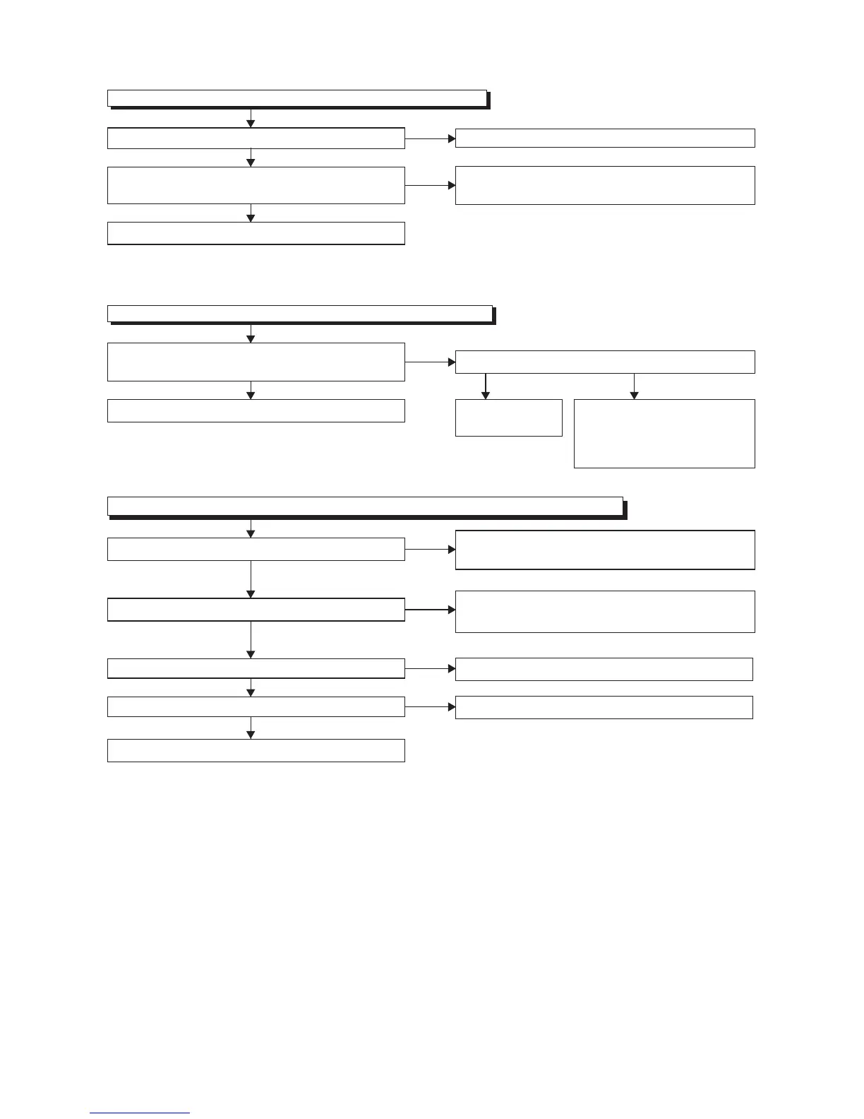
FLOW CHART NO.13
Hi-Fi audio can not be playbacked normally. (Hi-Fi E-E mode is normal.)
FLOW CHART NO.14
Audio can not be recorded normally in the linear audio mode. (E-E mode is normal.)
Is the audio signal inputted into Pin(13) of IC301?
Does the Bias oscillation circuit operate normally?
Is the audio signal outputted to Pin(11) of IC301?
Is the Playback Envelope signal outputted to Pin(33) of
IC451?
Replace P1(AV ASSEMBLY).
Is the Hi-Fi-H-SW signal inputted into to Pin(39) of IC451?
Ye s
Ye s
Ye s
Is the audio signal outputted to Pin(100) of IC301?
Ye s
Ye s
Ye s
No
No
No
No
Check the Hi-Fi-H-SW line between
Pin(39) of IC451 and Pin(19) of
IC501, and replace P1(AV
ASSEMBLY) if defective.
Check the line between Pin(78) of IC451 and Pin(13)
of IC301, and replace P1(AV ASSEMBLY) if defective.
Check the Bias oscillation circuit (
Q401,Q403,Q404,
Q405,Q406)
and replace P1(AV ASSEMBLY) if defective.
Replace P1(AV
ASSEMBLY).
Replace P1(AV ASSEMBLY).
No
Replace P1(AV ASSEMBLY).
No
FLOW CHART NO.12
Hi-Fi audio can not be recorded normally. (E-E mode is normal.)
Is the Hi-Fi-COM signal outputted to Pin(26) of IC451?
Is the line between Pin(8) of CN251 and Pin(26) of
IC451 normal?
Replace DECK ASSEMBLY (1B1).
Ye s
Ye s
No
Replace P1(AV ASSEMBLY).
No
Check the line between Pin(8) of CN251 and Pin(26)
of IC451, and replace P1(AV ASSEMBLY) if defective.
Replace DECK ASSEMBLY (1B1).
 Loading...