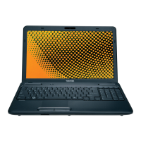
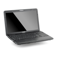
Do you have a question about the Toshiba Satellite C655D and is the answer not in the manual?
Details the key features and specifications of the Toshiba Satellite/Satellite Pro notebook PC.
Describes the various components that make up the computer's system unit.
Provides specifications and information about the 2.5-inch Hard Disk Drive used in the system.
Details the specifications and capabilities of the DVD Super Multi drive.
Explains the functions and operation of the computer's power supply unit.
Lists the types of batteries used in the computer and their specifications.
Provides an overview of the fault diagnosis procedures for Field Replaceable Units (FRUs).
Guides users through a step-by-step flowchart for identifying faulty FRUs.
Outlines troubleshooting procedures for power supply issues, including LED status checks.
Details procedures for diagnosing system board defects using message checks and test programs.
Explains how to troubleshoot Hard Disk Drive problems through message, partition, and format checks.
Provides troubleshooting steps for keyboard issues, including test programs and connector checks.
Covers troubleshooting for display problems, including external monitor checks and component checks.
Outlines procedures for troubleshooting the Optical Disk Drive, including cleaning and connector checks.
Details troubleshooting steps for the Local Area Network (LAN) connection.
Explains how to troubleshoot audio-related issues using test programs and connector checks.
Provides troubleshooting for the cooling module, including fan and connector checks.
Introduces the diagnostic programs and their classification into OPTION and DIAGNOSTIC TEST.
Explains how to run diagnostic tests, including Quick Test and Customization Test.
Details how to configure batch parameters and test item parameters within the diagnostic software.
Lists various subtests available for diagnosing system components like CPU, Memory, and Storage.
Covers CPU and FAN speed tests, including parameter settings and test results.
Describes tests for BIOS ROM and system memory, including pattern tests and extended memory checks.
Details diagnostic tests for HDD and ODD components, including read/write and seek functions.
Explains video tests, including text mode character tests and VGA mode tests.
Covers diagnostic tests for the LAN card, focusing on ID detection and MAC address.
Details diagnostic tests for peripherals like keyboard, mouse, and LEDs.
Lists error codes and their descriptions for various system components.
Provides a list of quick test items with their corresponding devices and comments.
Explains how to disassemble the computer and replace Field Replaceable Units (FRUs).
Details procedures for removing and installing the battery pack and bridge media.
Provides step-by-step instructions for removing and installing the memory module.
Covers the procedures for removing and installing the Hard Disk Drive (HDD).
Explains how to remove and install the ODD bay module and disassemble the ODD drive.
Details the process for removing and installing the keyboard and RTC battery.
Provides instructions for removing and installing the wireless LAN card.
Describes how to remove and install the top cover of the computer.
Covers the procedures for removing and installing the display assembly.
Details the steps for removing and installing the system board.
Explains how to remove and install the CPU cooling module and fan, including silicon grease application.
Provides instructions for removing and installing the CPU, including socket handling.
Details the procedure for removing and installing the display mask.
Explains how to remove and install the FL inverter board.
Covers the procedures for removing and installing the LCD module.
Provides instructions for removing and installing the LED module.
Details the process for removing and installing the CCD board and microphone.
Explains how to remove and install the power button board.
Covers the procedures for removing and installing the speakers.
Provides instructions for removing and installing the touchpad bracket.
Offers precautions and best practices for handling the LCD module to prevent damage.
Shows the front and back views of the system board, identifying key connectors and components.
Lists scan codes for various keys across different keyboard sets.
Illustrates the key layout for different regional keyboard configurations.
| Graphics | AMD Radeon HD 6310 |
|---|---|
| Display | 15.6-inch 1366x768 |
| Operating System | Windows 7 Home Premium |
| Weight | 5.5 lbs |
| Battery | 6-cell Lithium Ion |
| Processor | AMD E-Series Dual-Core |


