 Loading...
Do you have a question about the Toshiba TCB-IFCG1TLE and is the answer not in the manual?
| Brand | Toshiba |
|---|---|
| Model | TCB-IFCG1TLE |
| Category | Recording Equipment |
| Language | English |
Explains DANGER, WARNING, and CAUTION indications used in the manual.
Explains common safety marks like prohibition, mandatory, and caution.
Warning against modifying the product to prevent hazards.
Emphasizes using only specified spare parts for safety.
Cautionary note to keep children away from the equipment during work.
Guidance on insulation and wiring to prevent hazards.
Instructions for correct assembly and cable connection.
Procedure to check insulation resistance after repair.
Warning about potential electric shock when working with power ON.
Essential checks to perform after completing repair work.
Mandatory checks to perform after unit reinstallation.
Recommendation to wear gloves during repair work to prevent injury.
Caution regarding high temperatures after cooling/heating operation.
Provides an overview of troubleshooting for general-purpose devices.
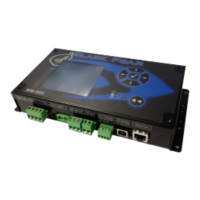
Lists the necessary devices and tools for the product's operation.
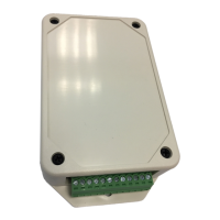
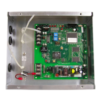
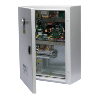
Procedure for inspecting the internal board of the TCB-IFCG1TLE unit.
Steps for performing common troubleshooting checks on the unit.
Troubleshooting guide for HA connector operation issues with AC units.
Diagnostic steps for when the conjunction function is not available.
Troubleshooting steps for problems with temperature measurement.
Guide for resolving issues with relay contact control from the center.
Troubleshooting I/O unreadability or no output when using the center controller.
Essential safety precautions for manual readers and product usage.
Defines the intended audience with required knowledge for the manual.
Outlines terms and conditions for product usage and warranty.
Details the warranty terms, coverage, and limitations.
Specifies limitations on the manufacturer's liability.
Defines acceptable conditions and purposes for product use.
Notes that product specifications are subject to change.
Critical safety warnings for installation and operation.
Important cautionary advice for installation and handling.
Introduction to the product's applications, functions, and specifications.
Overview of the product's capabilities and interfaces.
Details on how the product enables various controls and data reading.
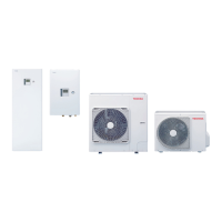
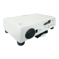
Lists the air conditioner models compatible with the product.
Technical specifications including power, dimensions, and operating conditions.
Diagram illustrating the external dimensions and mounting holes.
Pre-installation checks and requirements.
Lists all items included in the product package.
Specifies the types of wiring materials required for connections.
Details the necessary requirements for the AC adapter.
Instructions and guidelines for installing the product.
Describes different methods and orientations for product installation.
Specifies unsuitable locations for product installation.
Defines the required space for installation and maintenance access.
Guide to connecting power, earth, and signal wires to the unit.
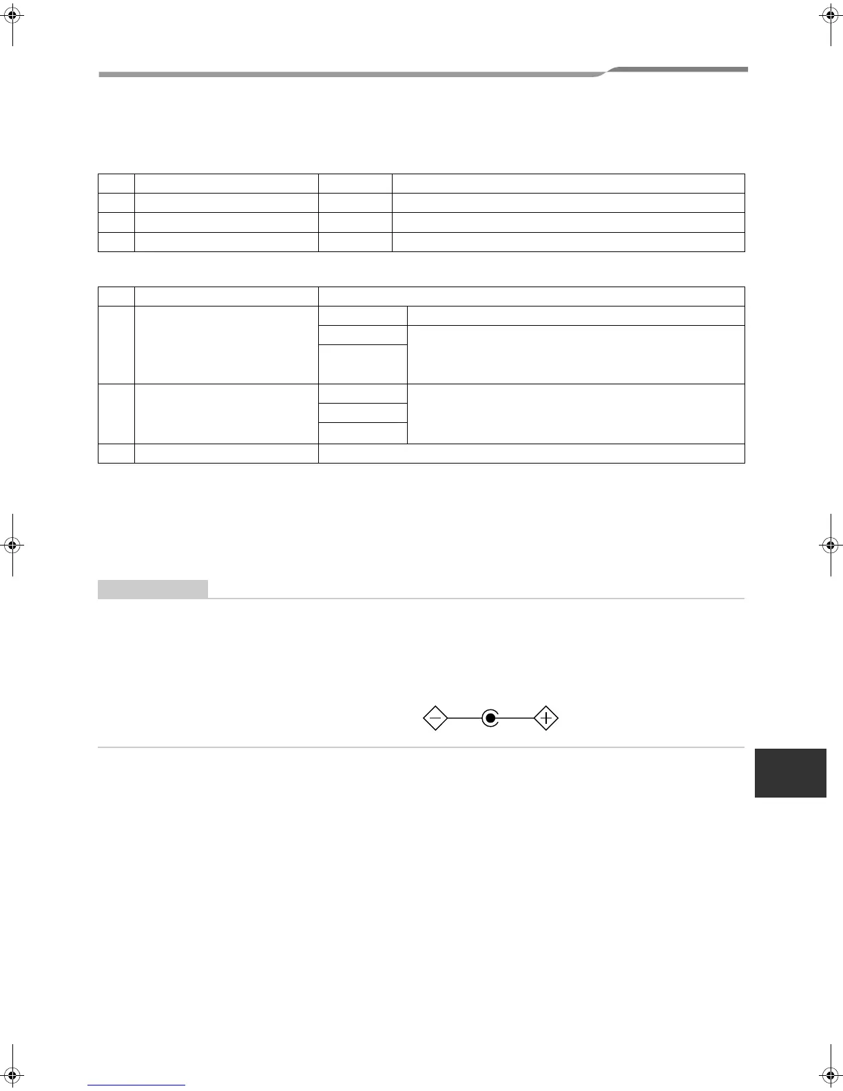
Important cautions regarding power line polarity and TCC-LINK lines.
Requirements for connecting the AC adapter to the main power supply.
Diagram showing correct connection of wires to terminals.
Specifies the required lengths for stripped signal and TCC-LINK wires.
Instructions on how to properly connect wires to wiring terminals.
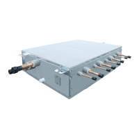
Illustrates examples of TCB-IFCG1TLE connections to the TCC-LINK network.
Information on TCC-LINK network connectivity options.
Procedure for connecting the shield of the TCC-LINK wire.
Steps for connecting HA compatible air conditioners with JEMA terminals.
Configuration procedures for DIP switches and operational settings.
How to set the terminator resistor for the TCC-LINK communication line.
Important notes on applying DIP switch settings for registration.
Details on setting the SW5 switch for various functions.
Procedure for setting unit addresses using SW1 and SW2 DIP switches.
Procedures for performing a trial operation and necessary checks.
Steps to complete before commencing the trial operation.
Important note regarding unique central control addresses for units.
Guide to operating the unit and verifying communication status.
Specifications for digital and analog input/output signals.
Details on the functions of digital and analog input/output signals.
Examples and explanations for connecting relay-controlled devices.
Specific functions and control options for DI4 and DI1 ports.
Lists available analog inputs and outputs and their specifications.
Detailed functions of analog input and output signals.
Description of terminal names and their input/output functions.
Precautions and guidelines for connecting external devices.
General safety measures to be observed during external circuit design.
General precautions to follow before starting the system.
Electrical requirements for connecting external circuits.
Method for connecting external relays for reinforced insulation.
Discussion on noise reduction and methods for relay connections.
Information regarding the direct output of relay contacts.
Illustrates various connection examples for relay contacts.
Diagrams showing examples of digital input connections.
Diagrams illustrating examples of analog input connections.
Requirement for connecting analog I/O points to the same earth point.
Diagrams showing examples of analog output connections.
Procedure for setting up the advanced conjunction function.
Explanation of the lighting conditions for the unit's LEDs.