1. System configuration
3
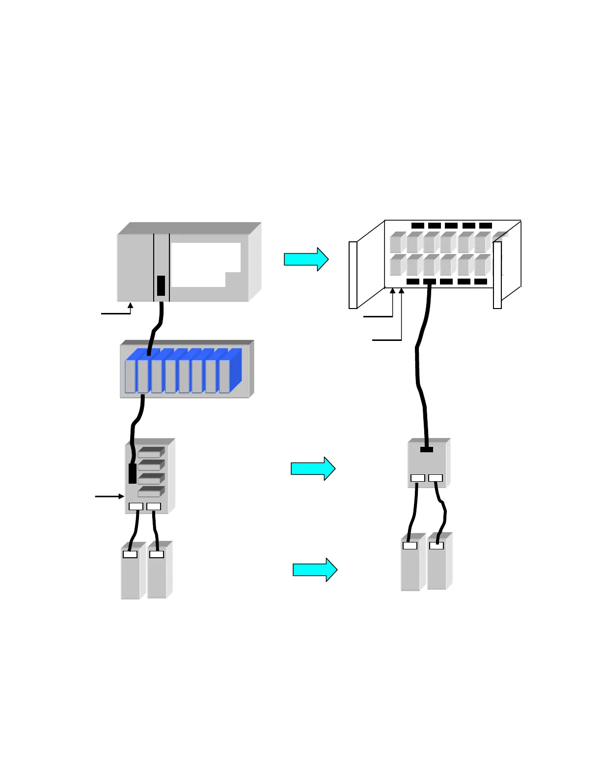
The loop system consists of the base unit, marshaling unit, and loop module. These
components are directly connected to the terminal block unit of the existing DPCS via the
dedicated cables. The DPCS system can be migrated to the DS system smoothly without
rewiring the external input-output lines.
High reliability can be achieved by online insertion/removal and redundancy of bus signals that
are essential for continuous operation of instrument control, and intelligence functions that
support diversity of signals from the site allow applications in a wide variety of fields.
Fig. 1.2 Loop system configuration
VCNUXn
Connector board unit
VTBUXn
Terminal block unit
Used as is
(including cable)
Replaced
Marshaling unit
UMASnn
New cable
Removed
Changeover unit
VSWUXn
Replaced
Loop control unit
VLCUXn
Continuous
control card
VLCPXn
ULCU12
Loop base unit
Loop module
SLP0n
System power
supply 24V
MV power
supply 24V
System power
supply 24V
MV power
supply 24V
 Loading...


