2. System component
7
Base unit
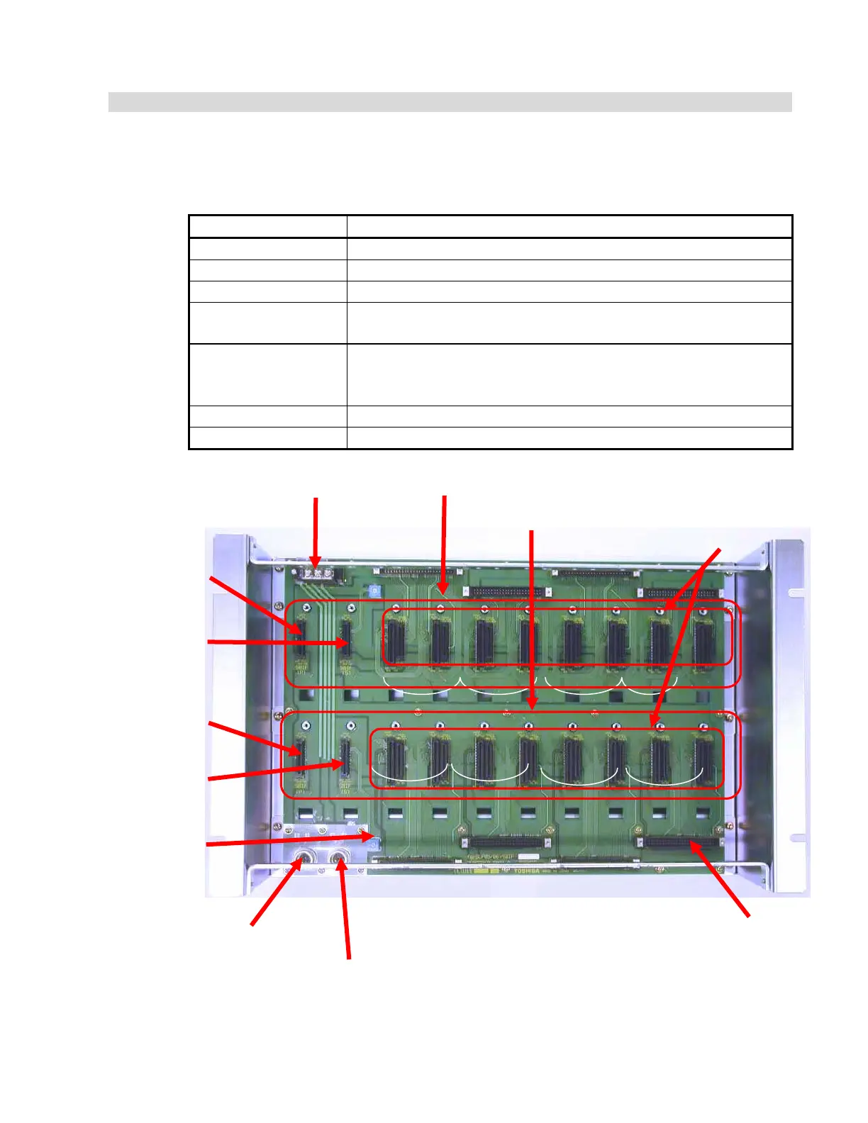
The base unit is a component to mount the base card and module to the housing. Fig. 2.1 is
the external view of the base unit.
Table 2.2 Base unit specification
Item Specification
Model name UIOU12
Mounting type Fixed to the housing with M4 screws (at 4 locations)
Applicable module SBIF3, SLP05, SLP06
Number of modules that
can be mounted
SBIF3 4 units (redundant, 2 pairs)
SLP05 or SLP06 16 units (redundant, 8 pairs)
Power connector For 24V system power supply: 1 piece
For 24V MV power supply: 1 piece
(If no SLP05 is installed in the unit, no MV power supply is required.)
Outside dimension
480W
×
289H
×
140Dmm
Weight 500g or less (single unit)
Fig. 2.1 ULCU12 external view
Marshaling unit VTBUX85C/P
cable connector
SBIF3 mounting
connector
(primary)
SBIF3 mounting
connector
(secondary)
SBIF3 mounting
connector
(primary)
SBIF3 mounting
connector
(secondary)
Serial bus terminal block
Unit address
setting switch
effective range
'1' to 'F'
SLP05/SLP06 Module
mounting connector
(Left: primary
Right: secondary)
By serial I/O unit
By serial I/O unit
24V system power supply cable
connector (SYS)
MV power supply 24V cable connector (MV)
 Loading...


