1. System configuration
2
Loop system configuration
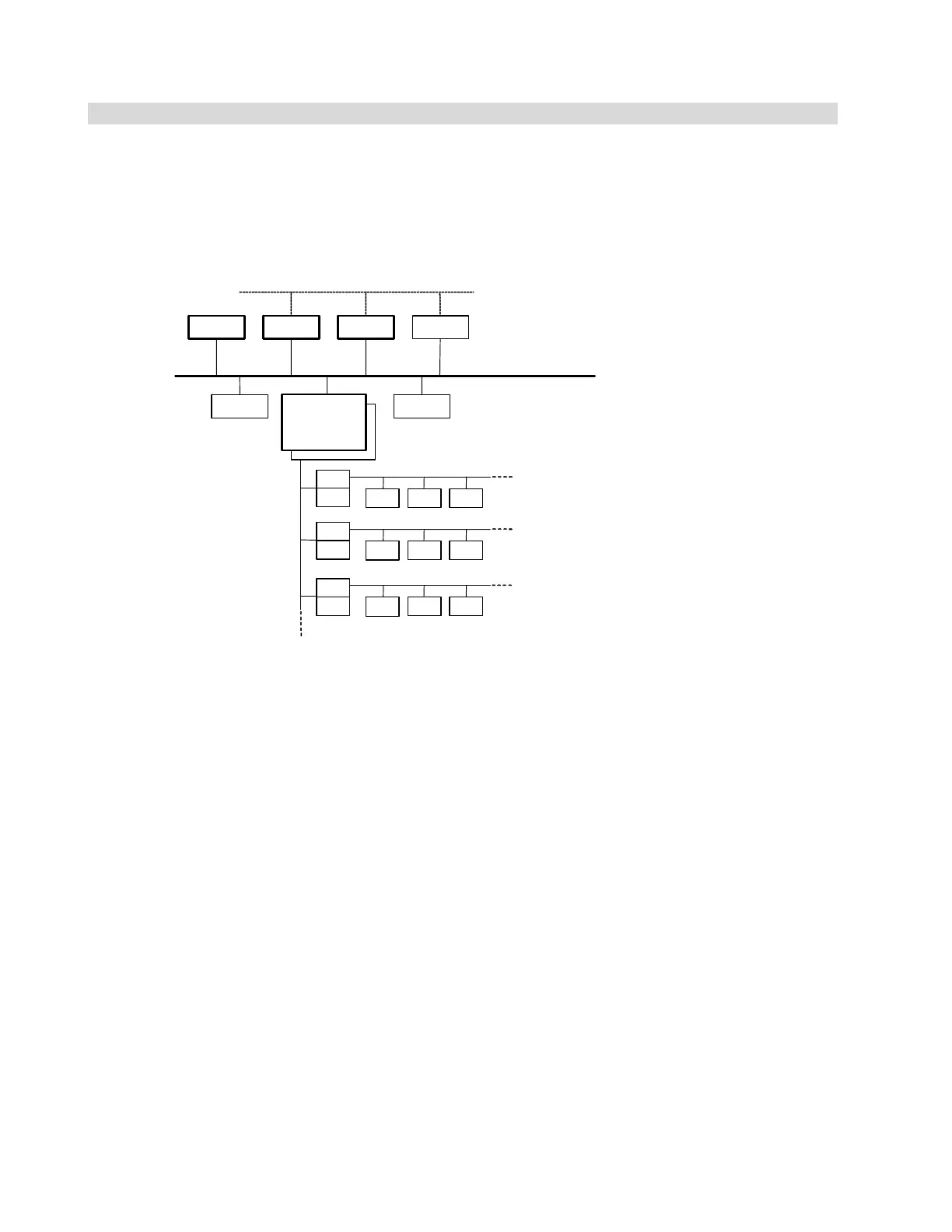
The loop system is connected to the main control system via the serial bus as shown in Fig. 1.1.
The loop system consists of the base unit, marshaling unit, and loop module, and is connected
to the terminal block unit of the existing DPCS, as shown in Fig. 1.2.
PLCS-DSPCS-DS
COMP
SVR OIS Tool
SBIF
SVR: Server
OIS: Operator station
(Monitoring operation screen)
COMP: Computer
PCS-DS: CIEMAC controller
PLCS-DC: PLC server
Host information system trunk line LAN
Monitoring control LAN Ethernet
DPCS
emulator
SBIF
LP LP LP
SBIF
SBIF
LP LP LP
SBIF
SBIF
AI TC RTD
I/O component
Loop system component
Loop system component
Main control system
Serial bus
Fig. 1.1 DPCS emulator system configuration
 Loading...


